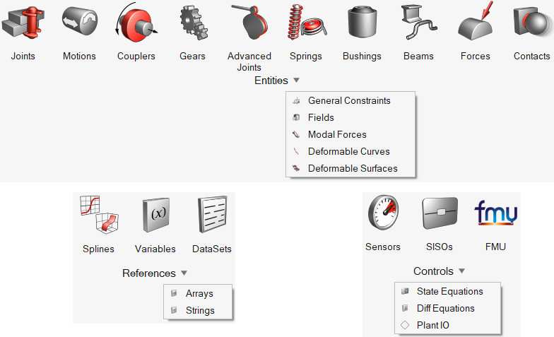
- Joints
Use the Joints tool to create and edit joints.
- Motions
Use the Motions tool to create motions and to edit the initial conditions, displacements, velocities, and acceleration of joints.
- Couplers
A Coupler entity defines an algebraic relationship between the degrees of freedom of two or three joints.
- Gears
Use the Gears tool to create a gear entity to relate the motion of two joints.
- Advanced Joints
Use the Advanced Joints tool to create and edit a set of special constraints called higher pair joints. Typically, these are constraints that involve a curve or surface on at least one of the two bodies.
- Spring Dampers
Use the Springs tool to create and edit SpringDampers.
- Bushings
Use the Bushings tool to create bushings and edit their connectivity, properties, and orientation rules.
- Beams
Use the Beams to create beams and edit their connectivity, properties, and orientations.
- PolyBeams
A PolyBeam is a series of beams that is defined through a series of points. PolyBeams can be used to represent slender beams, cables, and hoses.
- Forces
Use the Forces tool to create forces and to edit the orientation and properties of forces.
- FrequencyInputs
Defines excitation inputs to a Frequency Response Analysis.
- Contacts
Use the Contacts tool to specify the attributes of a contact force between two bodies.
- Contact Properties Editor
The Contact Properties Editor macro enables you to edit multiple contact force entities in a model simultaneously.
- General Constraints
Use the General Constraints tool to create a generic expression-based constraint.
- Fields
Use the Fields tool to create a compliant connection between two bodies where stiffness or damping in one direction can be a function of displacement in another direction
- Modal Forces
The Modal Forces tool allows you to include a disturbed force on a flexible body that exists in the modal form in the flexible body H3D.
- Surfaces
Use the Surfaces tool to create and edit surfaces.
- Deformable Curves
Use the Curves tool to create and edit deformable curves.
- Deformable Surfaces
Use the Surfaces and Surfaces from FEM tools to create and edit deformable surfaces.
- Spline2D/Curves
Use the Spline2D/Curves tool to create and edit curves.
- Spline3D
The Spline3D panel allows you to add and edit three dimensional spline data.
- Solver Variables
Use the Variables tool to create solver variables that can be used to create an algebraic expression of state variables, as well as other solver variables. This can then be referenced in function expressions throughout the solver input file.
- Datasets
Use the DataSets tool to create and edit datasets comprised of object types, such as real, string, boolean, integer, and options.
- Solver Arrays
Use the Arrays tool to create solver arrays and set solver array data. Solver array types include X array, Y array, U array, IC array, Plant Input array, and Plant Output array.
- Solver Strings
Use the Strings tool to create a solver string and set solver string data. A solver string provides a string that can be accessed within the model, for example, to pass into a user subroutine.
- Sensors
Use the Sensors tool to sense an event during simulation and to define a response to that event
- Control SISOs
Use the SISOs tool to set control SISO data. This data can be used to add additional states to the mechanical system being modeled.
- FMU
Use the FMU tool to add a Functional Mock-up Unit and connect it to a multibody model.
- Control State Equations
Use the State Equations tool to create and set control state equation data.
- Solver Differential Equations
Use the Diff Equations tool to set solver differential equations. These equations can be used to add additional states to the mechanical system being modeled.
- Orientation
Use the Orientation tool to align an entity along a particular direction.

