Dual Motor Electric Powertrain
Architecture
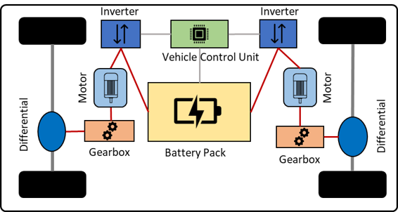
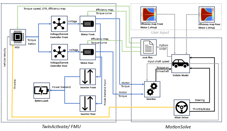
Powertrain Architecture in Twin Activate
- Dual Motor Superblock
- The Dual Motor superblock constits of two Permanent Magnet Synchronous Motors, two
Voltage-Current controllers, two Inverter/Converters, and a Battery Pack.
Figure 3. Dual Motor Superblock in Twin Activate 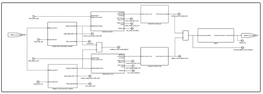
- Permanent Magnet Synchronous Motor
- A comprehensive model of the Permanent Magnet Synchronous Motor (PMSM) is
established based on its speed-torque characteristics and efficiency data. This
information is derived from an external efficiency map file
(.efmp), which contains the torque-speed and
torque-speed-efficiency characteristic curves of the motor. The data is
explicitly obtained through Look-up Tables in the form of
.mat files containing the relevant variables. This
approach allows for the incorporation of user-defined electric motor data in
vehicle simulations and ensures accurate calculation of power consumption.The Torque-Speed characteristic curve is particularly significant as it delineates the torque boundaries for both the motor's tractive (positive) and regenerative braking (negative) regions, as shown in the figure below. These boundaries illustrate the maximum positive and negative torque that the motor can generate. The PMSM motor's characteristics encompass two distinct regions: a constant torque region and a constant power region. The motor can deliver its maximum torque up to its rated speed, and beyond that point, it can supply its maximum power.
Figure 4. Torque-Speed Characteristic Curve 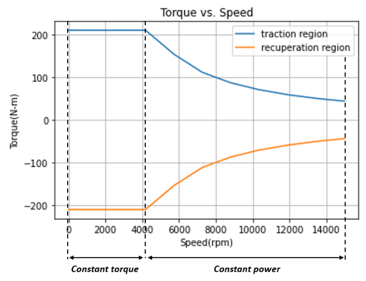
The Torque-Speed-Efficiency curve, also known as efficiency map, is responsible for providing the efficiency values for each motor depending on its operating region. It also contains information for the motor’s traction and regenerative braking region as shown in the figure below.Figure 5. Torque-Speed-Efficiency Characteristic Curve 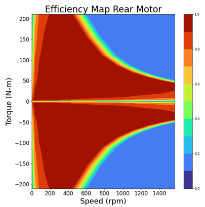
- Voltage-Current Motor Controllers
- The Voltage-Current controller block is used to control the AC supplied to the
motor. The control voltage depends on the vehicle speed, motor speed,
accelerator pedal input and battery state of charge. To determine the
appropriate voltage to apply to the motor, the controller employs Pulse Width
Modulation (PWM) and references Torque lookup tables. Additionally, the voltage
is subject to constraints imposed by the battery's state of charge (SOC).
Notably, when the battery SOC exceeds 80%, the controller prohibits regenerative
braking to safeguard the integrity of the battery cells, as such braking can
potentially inflict damage. Conversely, if the battery SOC falls below 20%, the
battery ceases to supply current, again as a protective measure for the battery
cells.
A PWM Look Up table is used to calculate the PWM value using vehicle speed and accelerator pedal input. The PWM value ranges from 0 to 250. The value 50 is used for coasting i.e. at this value the motor will output 0 torque. If the PWM value is less than 50 the motor acts as a generator and is in regenerative mode. A PWM value greater than 50 means the motor is providing positive torque for traction.
- Inverter/Converter Block
- The inverter/converter blocks are responsible for modeling the power losses resulting from the frequency conversion process executed by the motor control. It stands in between the motor and the battery pack and provides the final power demand of each motor.
- Battery Block
- The Battery model receives as input the combined power demand from both motors as input. It contains the required information to determine the capacity of the battery pack. It specifies the charging/discharging losses from the vehicle operation, to estimate the battery’s state of charge.
- Vehicle Control Unit Superblock
- The Vehicle Control Unit block consists of the Torque Demand Estimation, the Torque
Distribution Algorithm, and the Torque Ratio Calculation.
Figure 6. 1D Representation of the Vehicle Control Unit’block in Twin Activate 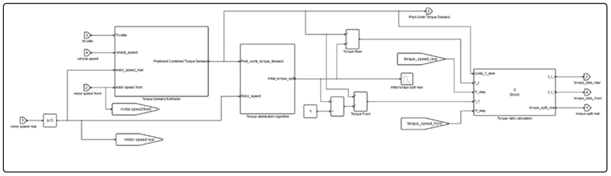
-
- Torque Demand Estimator Block
- The torque demand estimator defines the coasting region and regenerative
braking using One-Pedal Driving 1
to estimate the combined
motor torque demand. The coasting region consists of two distinct boundaries, as
illustrated in the accompanying image.
Figure 7. Upper and Lower coasting boundaries vs different vehicle velocities for throttle pedal mapping 
- In the figure above, the region above pcu, is the tractive region and the
region below the lower boundary (pcl) is the regenerative region. The coasting
band between these boundaries increases with vehicle speed. This expansion is a
deliberate design choice aimed at reducing the sensitivity of the accelerator
pedal at higher vehicle speeds. The regenerative torque in the powertrain can be
used to brake the vehicle in normal traffic conditions. The motor provides
enough negative torque to operate the vehicle with only one pedal in case of
city drives 1. At higher vehicle
velocities, the regenerative torque alone is not sufficient to stop the vehicle
and hence the friction braking should be used. The regenerative torque
percentage in this model changes with vehicle velocity as shown in the figure
below.
Figure 8. Regenerative Torque percentage of motor’s available torque vs vehicle speed 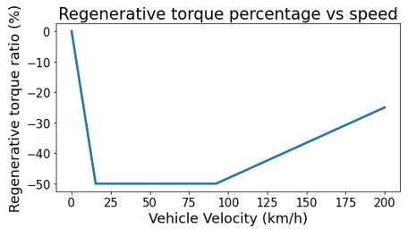
- Torque Distribution Algorithm Block
- Four different torque distribution strategies are available focused on battery
consumption reduction:
- Evenly Distributed (ED): a fixed 50-50% torque distribution is considered up to the point it cannot provide sufficient torque. When this limit is reached and additional torque is required, the system utilizes the remaining torque capacity of the motor with higher torque capabilities. Relies solely on motors’ maximum torque information (torque curve).
- Single Axle (SA): or overflow method – The torque is requested from a single motor while that motor can provide the entire torque. If a single motor cannot provide the torque, the residual is provided by the second motor – the torque request overflows to the second motor. Uses only motors’ maximum torque information (torque curve).
- Switch Threshold (ST): Calculates power losses
online, based on provided motors’ efficiency maps and switches between ‘SA’
and ‘ED’ to reduce power consumption 2, 3.Where,
- : motor speed
- : torque demand
- : power losses originating from single (rear) motor operation
- : power losses originating from dual motor 50-50 torque distribution operation
- : rear motor efficiency = , determined by motor's characteristic efficiency map
- : front motor's efficiency = , determined by motor's characteristic efficiency map
- : rear motor's efficiency = , determined by motor's characteristic efficiency map
- : small number to avoid division by zero
Algorithm
At every time step:- Calculate both ,
- If
<
set torque bias = 1
Else: set torque bias = 0.5
- Optimal Torque Ratio (OTR): Offline exhaustive
search method to determine optimal torque distribution for all torque-speed
scenarios within motors’ capabilities 4. An optimal
torque map is formed in advance, automatically utilizing the motors’ torque
limits and efficiency data. Total electric power consumption is minimized by
targeting each motor’s most efficient operating point. It is then used as a
Look-up Table to select the most efficient torque split ratio in the range
0-100%.
The method considers all possible combinations of motor angular speeds and torques within the range of each motors’ capabilities, which are defined by the .efmp files. Then, calculates the overall system efficiency using the following equation, for every possible torque split ratio. Outside of motors’ torque- speed range, the map provides the torque ratio that leads to maximum combined torque. Finally, the torque split ratio that results in optimum efficiency is selected, thus forming the optimal torque ratio map.
Where,- : torque split ratio
- : combined torque demand on both motors
- : front/ rear axle’s angular velocity, assumed equal
-
: front/ rear motor’s efficiency as a
function of
,
,
Calculated in python, by interpolating motor’s efficiency map
- : small number used to handle arithmetical errors, such as division by zero
The figure below shows the 3D map that contains the optimal torque ratios for the default motor configuration. It is generated automatically before every simulation based on the motors’ provided data by the .efmp files.Figure 9. Optimal torque map, specified by the Optimal Torque Ratio strategy 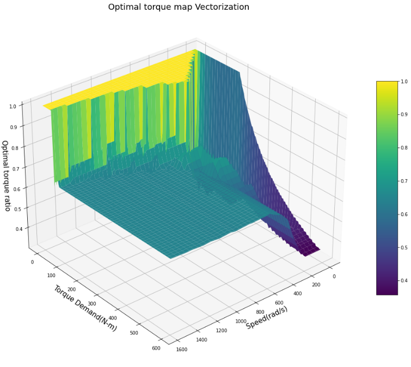
- Torque Ratio Calculation Block
- Determines the final motor’s torque ratio considering parameters such as
motors’ capabilities and vehicle’s state (tractive or regenerative braking). The
motor’s torque ratio, as opposed to torque split ratio, is the percentage of
motor’s torque utilization that is determined by the VCU and is indited by the
following
equation:Where,
- : motor's torque
- : motor’s maximum torque as a function of speed
The torque ratio can receive values in the range of [-100, 100], where positive values depict motor operation in tractive mode and negative values regenerative braking mode.Note: The complete Twin Activate diagram of the powertrain model can be accessed from: <install_dir>\ hwdesktop\hw\mdl\mdllib\Common\FMU_Library\Motor\FMU_source\Activate_Models.
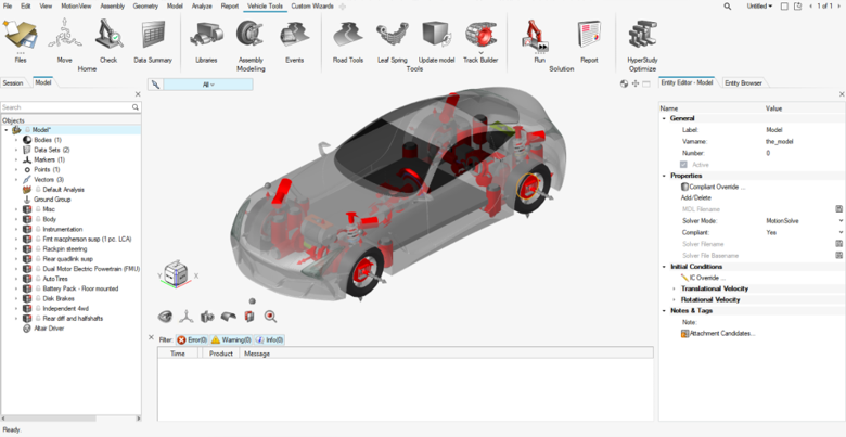
Powertrain Model in MotionView
In the MotionView MDL system, the motors, inverters, and battery are represented as rigid bodies including their mass and inertia properties, which are a significant portion of BEV’s total mass and inertia. Two forces under Gearbox systems represent the driving torques attached to the driveshaft. Four Solver variables connect the FMU channels to the Altair Driver. Datasets contain crucial information on motor bodies’ properties. Moreover, each motor’s bushings are provided, that define the positions where the motors are based. Finally, the Altair Driver uses a Feedback Controller for speed and acceleration control.
- Datasets
-
- Motor Properties
-
The torque distribution algorithms found on the VCU, rely on real motor torque-speed-efficiency data provided by external efficiency map files (.efmp). These files are a representation of the motors’ Torque-Speed and Torque-Speed-Efficiency characteristic curves. The paths pointing to these files are received as inputs in the Motor Properties Dataset.
- Template
-
- Evaluate Motor Properties
- It is responsible for the initialization of an internal script
(MotorProperties.py) before every simulation, used to:
- Read the Teimorbit format .efmp file.
- Extract motor properties.
- Generate .mat files specific to the .xml file and store them in the run folder.
- Assign the correct .mat file paths/variables in the FMU parameters section.
- And finally, execute – if selected - the OTR torque distribution strategy to generate the optimal torque ratio map.
- Solver Variables
-
Entities Type Description Comments Driver Throttle Output Attachment solver variable Throttle signal from driver 0-1 Driver Clutch Output Attachment solver variable Clutch signal from driver Not used in the model but required by the driver’s attachment Driver Gear Output Attachment solver variable Gear signal from driver Not used in the model but required by the driver’s attachment FMU Torque - rear/front Solver Variable Rear/ Front motor output torques N-mm FMU Omega rear/front Solver Variable Rear/ Front motor output wheel velocities rad/s Torque Ratio - rear/front Solver Variable Rear/Front motor speed torque utilization 0-100 Vehicle Longitudinal Velocity m/s Solver Variable Vehicle’s longitudinal velocity m/s Battery SOC Solver Variable Battery’s State-Of-Charge 0 - 1 Combined battery power demand Solver Variable The combined battery power demand from both motors Watt Combined motor torque demand Solver Variable The combined torque demand from both motors N-m Predicted combined torque demand Solver Variable The combined motor torque demand predicted by the VCU N-m Torque split - rear Solver Variable Rear-front torque distribution, where 100% represents rear-wheel drive and 0% signifies front-wheel drive. 0 - 100 - FMU Entity
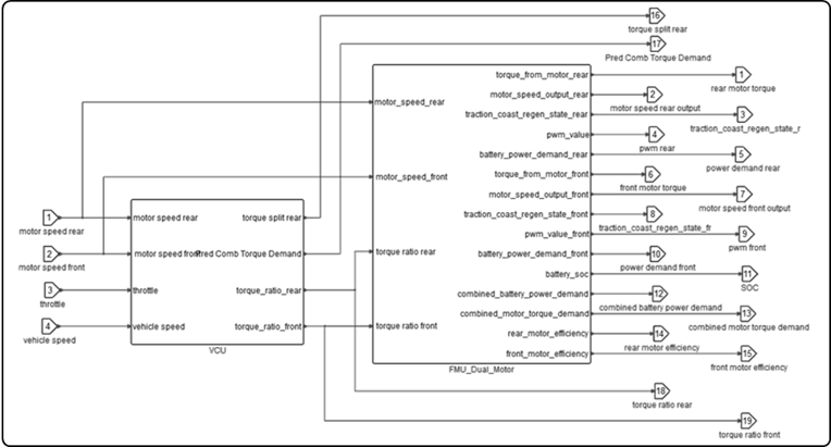
- Represents the FMU of the Dual Motor Electric Powertrain with inputs, outputs,
parameters, and solver settings. The inputs of the FMU powertrain can be customized
and you are free to change the system, however some inputs and outputs need to be
present to correctly simulate a driver event. The schematic below shows the necessary
inputs and outputs of the FMU powertrain block. The powertrain receives throttle,
transmission input shaft speed front and rear, vehicle speed and outputs torque.
Figure 11. Dual Electric Motor Powertrain with VCU Co-simulation in Twin Activate 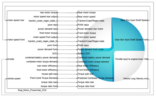
- FMU Inputs
-
Connections Description Units Comments Motor speed rear Rear Gearbox input shaft speed rad/s Motor speed front Front Gearbox input shaft speed rad/s Throttle from driver The accelerator pedal’s input from driver 0 - 100 Unit conversion required from MV’s 0-1 to FMU’s 0-100 Vehicle speed Vehicle’s longitudinal velocity m/s Unit conversion required from MV’s mm/s to FMU’s m/s - FMU Outputs
-
Connections Description Units Comments Torque from rear motor The output torque from the rear motor N-m Unit conversion required from FMU’s N-m to MV’s N-mm Motor speed rear output rear motor shaft speed rad/s Traction Coast Regen State rear Integer value that shows the operating mode of the rear motor: -1 indicates that powertrain is in regenerative braking mode, 0 means it is operating in coasting band and a value of 1 indicates that the motor is operating in tractive region -1, 0, 1 PWM rear value It corresponds to the pulse width modulation value which can be converted to voltage applied to the rear motor 0-250 Power demand rear motor Power demand from rear motor to the battery Watt Torque from front motor The output torque from front motor N-m Unit conversion required from FMU’s N-m to MV’s N-mm Motor speed front output Front motor shaft speed rad/s Traction Coast Regen State rear Integer value that shows the operating mode of front motor: -1 indicates that powertrain is in regenerative braking mode, 0 means it is operating in coasting band and a value of 1 indicates that the motor is operating in tractive region -1, 0, 1 PWM front value It corresponds to the pulse width modulation value which can be converted to voltage applied to the front motor 0 - 250 Power demand front motor Power demand from front motor to the battery Watt Battery SOC The state of charge of the battery 0 - 1 Combined battery power demand The combined battery demand from both motors Watt Combined Motor Torque Demand The combined torque demand from both motors N-m Unit conversion required from FMU’s N-m to MV’s N-mm Rear motor efficiency Rear motor’s efficiency 0 - 1 Front motor efficiency Front motor’s efficiency 0 - 1 Rear torque spit Torque distribution, using rear motor as a reference point 0 - 100 Predicted combined torque demand The combined motor torque demand predicted by the VCU N-m Unit conversion required from FMU’s N-m to MV’s N-mm Torque ratio rear Rear motor’s torque ratio 0 - 100 Torque ratio front Front motor’s torque ratio 0 - 100 - FMU Parameters
-
Parameters Description Units converter_efficiency Converter’s efficiency value inverter_efficiency Inverter’s efficiency value num_modules_pack_parallel Number of module packs in parallel num_cells_per_module_parallel Number of cells per module in parallel capacity_cell Cell’s capacity Amp-hours battery_charging_losses Coefficient to determine battery charging losses while at recuperation region nominal_voltage_cell Cell’s nominal voltage V num_cells_per_module_series Number of cell rows per module num_modules_pack_series Number of module packs rows SOC_initial Initial State-Of-Charge level (%) battery_discharging_losses Coefficient to determine battery discharging losses while at tractive region emotor_efficiency_scale Parameter to enable efficiency scaling max_pwm Maximum PWM value pwm_zero_torque PWM value corresponding to 0 torque output SOC_limit_high Upper limit for SOC SOC_limit_low Lower limit for SOC max_vehicle_speed Vehicle’s maximum velocity m/s coast_m Polynomial degree to determine coasting region coast_phi At what pedal value coasting is desired coast_ch Range of coasting to define pcl and pcu values max_pedal Maximum throttle value 0 - 100 traction_gamma Polynomial degree to define the correlation between throttle and torque ratio for the traction region regen_psi Order of polynomial to define the correlation between throttle and torque ratio for the regenerative region traction_max Percentage of maximum available torque N-m pedal_0_regen_percent 1-4 These parameters define the percentage of regenerative braking contribution to total braking as a function of velocity. Specifically, you can specify the regenerative braking percentage to determine the three sections of Figure 8. pedal_0_vx 1-4 These parameters specify the corresponding velocities at specific regenerative braking percentages. Specifically, they are used to define the velocity values that designate the three sections of Figure 8. Path char Warning: This parameter is automatically updated, it should not be manually modified.Mat file path that contains both motor characteristics, such as rated and maximum speed, rated torque Vcu_type Set VCU torque distribution strategy: 1: ED
2: SA
3: ST
4: OTR
matfilename - Rear Motor data mat file path Warning: This parameter is automatically updated, it should not be manually modified.Path pointing to rear motor’s mat file. Appearing multiple times in the FMU. matfilename - Front Motor data mat file path Warning: This parameter is automatically updated, it should not be manually modified.Path pointing to front motor’s mat file. Appearing multiple times in the FMU. matfilename - Optimal Torque ratio map mat file path Warning: This parameter is automatically updated, it should not be manually modified.Path pointing to optimal torque ratio .mat file path. matvarname Warning: This parameter is fixed, it should not be altered.Refers to the rear, front motor or optimal torque ratio map .mat files’ variable names, used for data extraction. It appears multiple times in the FMU.
- Motor Front/Rear Systems
- Includes the integrated motor-inverter unit.
- Bodies
- Motor/Engine - Represents the lumped mass and inertia of each motor in a non-operating condition. The motor’s output shaft is assumed to be hard coupled with gearbox input shaft and hence their speed is going to be the same. The motor’s shaft and its rotation are not modeled. Since the inertia of the rotating shaft is not modeled, this inertia can be added in other rotating elements in the driveline.
- Motor Mounts
- Motors are attached to chassis by four bushings. The mount locations must be provided on the attachment body by specifying the coordinates of the mounts and the orientation of the bushings specified using the vectors corresponding to each mount.
- Solver Variables
-
Entities Type Description Comments FMU Torque Solver Variable Motor output torque from FMU N-mm FMU Omega Solver Variable Motor output wheel velocity from FMU rad/s Throttle input to motor 100 Solver Variable Throttle input from driver 0-100 FMU Power demand motor Solver Variable Motor power output W Traction/Coast/Regen state Solver Variable Integer value that shows the operating mode of motor: -1 indicates that powertrain is in regenerative braking mode, 0 means it is operating in coasting band and a value of 1 indicates that the motor is operating in tractive region -1, 0, 1 PWM value Solver Variable It corresponds to the pulse width modulation value which can be converted to voltage applied to the rear motor 0-250 Motor Efficiency Solver Variable Motor’s efficiency 0-1
- Gearbox Front/Rear Systems
-
- Bodies
- Gearbox – Contains the mass and inertia properties of gearbox body in a non-operating condition. Gearbox is also assumed to be directly attached to the motor body, with the usage of a fixed joint. The motor’s output shaft is assumed to be hard coupled with gearbox input shaft and hence their speed is going to be the same.
- Datasets
-
- Gearbox Data
-
Label Description Final Drive Ratio Differential’s final stage of gear reduction ratio, used to calculate the final drive torque. Gearbox Efficiency Gearbox’s overall efficiency, used to calculate the final drive torque.
- Solver Variables
-
Entities Type Description Comments Torque from Gear Box Solver Variable Mathematical expression used to calculate gearbox’s final output torque. N-mm Gear Box Input Shaft Speed Solver Variable Mathematical expression used to calculate gearbox’s input shaft speed. rad/s - Forces
- Gearbox Output Torque - Represents the powertrain’s output torque on the differential’s carrier body. The torque is calculated by the ‘Torque from Gear Box’ Solver Variable expression.
- Battery Pack
- If the battery pack module has been selected from the Assembly Wizard, it can be
found as a separate system, out of the primary Dual Motor Powertrain system. It includes:
- Bodies
- Battery Pack - Represents body's mass and inertia properties.
- Battery Mounts
- Battery is attached to chassis by four bushings. The mount locations must be provided on the attachment body by specifying the coordinates of the mounts and the orientation of the bushings specified using the vectors corresponding to each mount.
Access the Electric Powertrain for Full Vehicle Models
- The Vehicle Tools extension must be loaded.
- From the menu bar, select .
- Load the Vehicle Tools extension by sliding the Load button to the right.The Vehicle Tools ribbon is add in MotionView.
Figure 12. 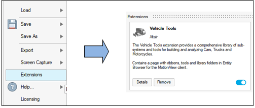
- In the Vehicle Tools ribbon, click the Assembly tool to open the Assembly Wizard.
- Select the Full Vehicle with Driver model and click
Next.
Figure 13. Select Model Type 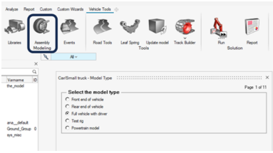
- Choose the Four wheel drive driveline configuration and then
select the Dual Motor Electric Powertrain (FMU), which is listed
in the Powertrain drop-down menu.
Figure 14. 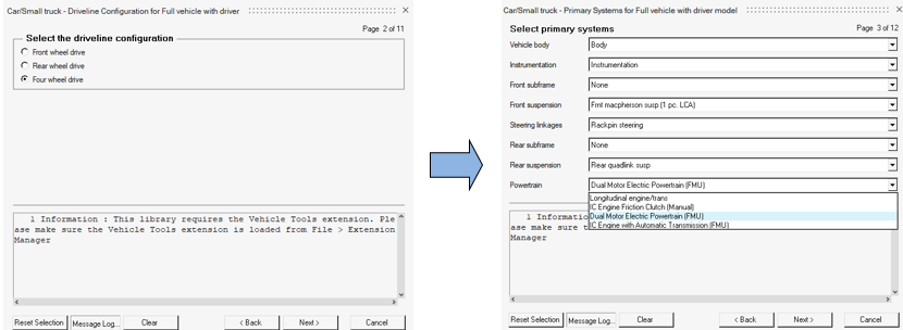
- After selecting the vehicle’s powertrain type, you can also opt for a Battery Pack
body.
Figure 15. 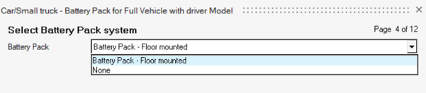
Modifying the FMU Powertrain
You can easily customize the default powertrain specifications to suit a specific requirement by adjusting parameters within the FMU's parameter section. Throttle response, regenerative braking contribution to total braking, and battery’s capacity are the main parameters that can be altered. The vehicle’s behavior parameterization is mainly divided into two main sections regarding motor specifications and regenerative braking.
$---------------------------------------------------------------------ALTAIR_HEADER
[ALTAIR_HEADER]
FILE_TYPE     =  'efmp'
FILE_VERSION  =  1.0
FILE_FORMAT   =  'ASCII'
$--------------------------------------------------------------------------UNITS
[UNITS]
(BASE)
{length  force      angle       mass    time}
'm'   'newton'   'degrees'   'kg'    'sec'
(USER)
{unit_type    length  force  angle  mass  time  conversion}
'rpm'          0       0      1      0     -1     6.0
'torque'       1       1      0      0      0     1.0
$-------------------------------------------------------------------------Motor Details
[EFFICIENCY_MAP]
(X_DATA)
{speed}
+0.000000E+00
+8.537861E+01
+3.415145E+02
+7.684075E+02
+1.366058E+03
+2.134465E+03
+3.073630E+03
+4.183552E+03
+5.728759E+03
+7.273966E+03
+8.819173E+03
+1.036438E+04
+1.190959E+04
+1.345479E+04
+1.500000E+04
$-------------------------------------------------------------------------Efficiency
(YZ_DATA)
{a b c d e f g h i j k l m n o p}
+0.000000E+00	+0.000000E+00	+0.000000E+00	+0.000000E+00	+0.000000E+00	+0.000000E+00	+0.000000E+00	+0.000000E+00	+0.000000E+00	+0.000000E+00	+0.000000E+00	+0.000000E+00	+0.000000E+00	+0.000000E+00	+0.000000E+00	+0.000000E+00
+1.218756E+00	+0.000000E+00	+8.323871E-01	+8.348879E-01	+8.207778E-01	+7.975356E-01	+7.686840E-01	+7.357196E-01	+6.984794E-01	+6.564586E-01	+6.174752E-01	+5.872302E-01	+5.100155E-01	+4.613040E-01	+4.190096E-01	+3.827032E-01
+4.875026E+00	+0.000000E+00	+8.814608E-01	+9.318992E-01	+9.365690E-01	+9.319987E-01	+9.231622E-01	+9.104752E-01	+8.949006E-01	+8.728267E-01	+8.505602E-01	+8.328031E-01	+8.007164E-01	+7.678712E-01	+7.359362E-01	+7.055424E-01
+1.096881E+01	+0.000000E+00	+8.376550E-01	+9.363595E-01	+9.546854E-01	+9.582281E-01	+9.565427E-01	+9.522109E-01	+9.459273E-01	+9.365793E-01	+9.269542E-01	+9.121204E-01	+8.934734E-01	+8.735761E-01	+8.534340E-01	+8.334711E-01
+1.950010E+01	+0.000000E+00	+7.779298E-01	+9.228859E-01	+9.543095E-01	+9.639408E-01	+9.664942E-01	+9.656404E-01	+9.628304E-01	+9.575883E-01	+9.519336E-01	+9.419017E-01	+9.290871E-01	+9.152123E-01	+9.008979E-01	+8.863836E-01
+3.046891E+01	+0.000000E+00	+7.155875E-01	+9.027567E-01	+9.474120E-01	+9.628555E-01	+9.686488E-01	+9.702265E-01	+9.695124E-01	+9.667733E-01	+9.626870E-01	+9.544688E-01	+9.441605E-01	+9.329200E-01	+9.210782E-01	+9.086153E-01
+4.387523E+01	+0.000000E+00	+6.563856E-01	+8.792230E-01	+9.373423E-01	+9.584760E-01	+9.673843E-01	+9.709935E-01	+9.718605E-01	+9.707183E-01	+9.671191E-01	+9.594001E-01	+9.499134E-01	+9.392034E-01	+9.267406E-01	+9.036660E-01
+5.056248E+01	+0.000000E+00	+6.314770E-01	+8.682518E-01	+9.322428E-01	+9.559373E-01	+9.662057E-01	+9.706858E-01	+9.721578E-01	+9.716095E-01	+9.679095E-01	+9.601471E-01	+9.505474E-01	+9.390330E-01	+9.168608E-01	NaN
+5.919049E+01	+0.000000E+00	+6.030777E-01	+8.548915E-01	+9.257981E-01	+9.525703E-01	+9.644708E-01	+9.699594E-01	+9.721433E-01	+9.722637E-01	+9.681889E-01	+9.601339E-01	+9.496912E-01	+9.281723E-01	NaN	NaN
+7.075054E+01	+0.000000E+00	+5.703066E-01	+8.382680E-01	+9.174994E-01	+9.480588E-01	+9.619707E-01	+9.686980E-01	+9.717496E-01	+9.726024E-01	+9.676793E-01	+9.586062E-01	+9.380106E-01	NaN	NaN	NaN
+8.699840E+01	+0.000000E+00	+5.315730E-01	+8.168210E-01	+9.063657E-01	+9.418017E-01	+9.583267E-01	+9.666546E-01	+9.708084E-01	+9.720695E-01	+9.655065E-01	+9.453839E-01	NaN	NaN	NaN	NaN
+1.114960E+02	+0.000000E+00	+4.823827E-01	+7.864047E-01	+8.898433E-01	+9.321732E-01	+9.524598E-01	+9.630950E-01	+9.688285E-01	+9.694182E-01	+9.487760E-01	NaN	NaN	NaN	NaN	NaN
+1.540854E+02	+0.000000E+00	+4.040688E-01	+7.291549E-01	+8.564716E-01	+9.117700E-01	+9.393322E-01	+9.544374E-01	+9.631752E-01	+9.458014E-01	NaN	NaN	NaN	NaN	NaN	NaN
+2.104600E+02	+0.000000E+00	+3.119294E-01	+6.435543E-01	+8.010837E-01	+8.758160E-01	+9.149455E-01	+9.372630E-01	+9.507810E-01	NaN	NaN	NaN	NaN
$-------------------------------------------------------------------------ENGINE
[TORQUE_CURVE]
(DATA)
{speed torque}
+0.000000E+00	+2.104599E+02
+8.537861E+01	+2.104600E+02
+3.415145E+02	+2.104600E+02
+7.684075E+02	+2.104600E+02
+1.366058E+03	+2.104600E+02
+2.134465E+03	+2.104600E+02
+3.073630E+03	+2.104600E+02
+4.183552E+03	+2.104600E+02
+5.728759E+03	+1.540854E+02
+7.273966E+03	+1.114960E+02
+8.819173E+03	+8.699840E+01
+1.036438E+04	+7.075054E+01
+1.190959E+04	+5.919049E+01
+1.345479E+04	+5.056248E+01
+1.500000E+04	+4.387523E+01
+1.500000E+04	+0.000000E+00
Throttle response within the traction region is influenced by two key parameters: ‘ ’ and ‘ ’. The right setting should offer the correct balance between smoothness and responsiveness. Fine-tuning these settings can result in an improved driving experience by providing the desired balance between these two factors.
You can also determine the vehicle’s regenerative braking amount by handling the relevant parameters. The equations that determine the regenerative braking amount are derived by 1. Regenerative braking distribution is fixed by default to ’60-40’ front-rear. The traction, coasting and regeneration region for motor mapping are described in detail in 1. Vehicle’s coasting boundaries ‘ ’ and ‘ ’ are defined by the parameters ‘ ’, ‘ ’, ‘ ’ and vehicle’s maximum velocity ‘ ’. Vehicle’s regenerative amount for different speeds is determined by a map used as a Look-up table. ‘ ’ and ‘ ’ are the parameters responsible for the speed – regenerative braking mapping. Finally, ‘ ’ is used to define the correlation between throttle and output torque.
Limitations
- The rotational inertia of the motor’s shaft should be added in the rotating bodies in the driveline.
- The default motor configuration assumes that the motor regenerative region is the same as tractive, in terms of efficiency mapping.