Limited Slip Differential (LSD) is a type of
differential that allows the individual drive shafts (left/right) to rotate at different
speeds but provides an option to limit the difference between the two. This is accomplished by
providing a mechanism that resists the speed differential between the shafts. This could be a
clutch or viscous coupling-based design.
LSD in MotionView Vehicle Libraries
In MotionView’s Car/Small truck and Heavy truck library, a viscous coupling is used between
the left-right drive shafts to model the slip limit.
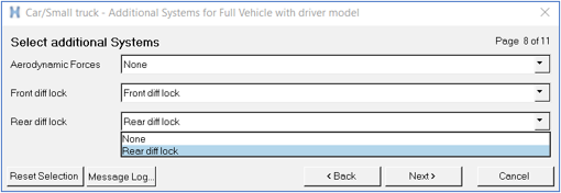
LSD can be included while building a vehicle model using the assembly wizard. The selection
is available under Front diff lock and/or Rear diff lock on the “Additional Systems for Full
Vehicle with driver model” page:Figure 1. Differential lock selection for a 4wd configuration
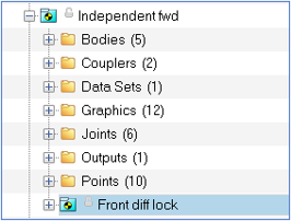
Once the model is built, the diff locks system is created under the respective axle’s drive
System:Figure 2. Differential lock within the Drive system
LSD Model
The limited slip differential is modeled using a simple rotational force/torque. The torque
is an expression that is a function of:
A damping coefficient (DAMP_COEFF)
Delta of rotational speeds of the shafts (OMEGA_DIFFERENCE)
Desired allowable difference between shafts’ rotational speeds
(ALLOWABLE_SPEED_DIFFERENCE)
A numerical switch (1, 0) that is used to switch On/Off the locking torque
(LOCK_STATE)
The torque acts between the Left and Right halves of the drive shaft.
Interface
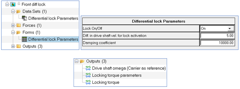
For easy manipulation of the diff lock parameters, a Form has been provided in the system
which can be used to edit the values. Outputs are also available for plotting during result
post-processing.Figure 3. Interface for editing parameters and Outputs