CVT Model
Symbols used:
 = p, for primary pulley
= s, for secondary pulley
| Radius Ratio [State] |  |
Pulley’s Minimum Radius |  |
| Pulley’s inertia |  |
Pulley’s Maximum Radius |  |
| Pulley’s Torque |  |
Pulley’s Axial displacement |  |
| Pulley’s Running radius |  |
Maximum Torque |  |
| Pulley’s RPM |  |
||
| Belt mass |  |
Distance of flyweight from axis |  |
| Belt length |  |
Flyweight mass |  |
| Pulley’s distance |  |
Number of rollers |  |
| Pulley’s Half angle |  |
Primary pulley Sheave angle |  |
| Wrap angle |  |
Primary sheave ramp angle |  |
| Helix angle |  |
Internal spring stiffness |  |
| Helix radius |  |
Internal spring preloads |  |
| Rotational Stiffness of secondary spring |  |
Rotational spring preload |  |
| Static Friction Coefficient |  |
Dynamic Friction Coefficient |  |
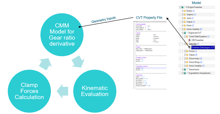
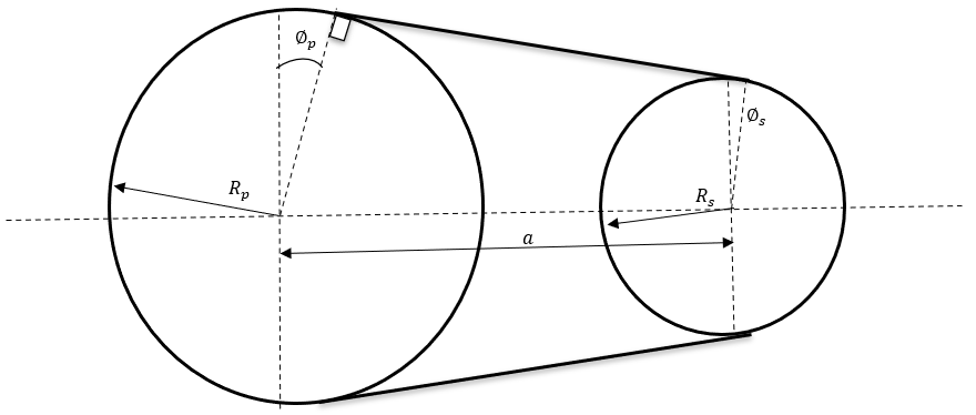
1. Kinematic Evaluation
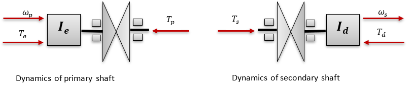
The input to primary pulley comes from engine RPM and are related as:

The output of the secondary pulley is input to the gearbox and are related as:


 therefore you can use the Newton Raphson method to solve for
running radii and angle .
therefore you can use the Newton Raphson method to solve for
running radii and angle .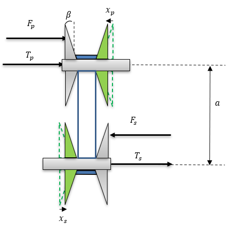
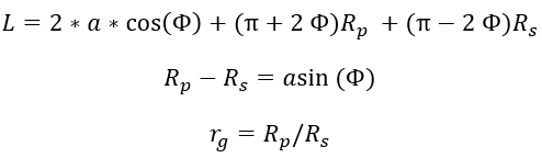
Once you have running radii and angle you can calculate the pulley’s axial displacements and wrap
angles as follows:
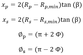
with respect to radius ratio: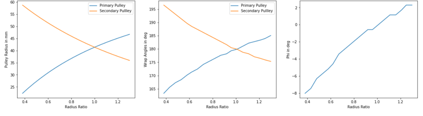
2. Clamp For Calculation
The CVT model is set such that it can model mechanical, electric, and hydraulic CVT. By default, MS models a mechanical CVT based on following parameter in CVT property file.
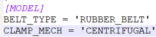

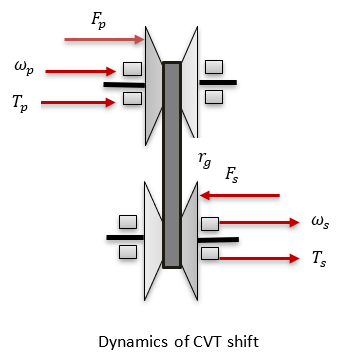
- Primary Pulley Clamping Force:
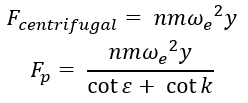
- The ‘CENTRIFUGAL’ mechanism is used mostly in scooters where the clamping force is
generated using the fly weights which rotates about the engine shaft and along the
primary pulley sheave. The sheave has a ramp profile which converts the centrifugal
force generated by flyweights into the clamping force.
Figure 7. Shift mechanism of roller weights on ramp 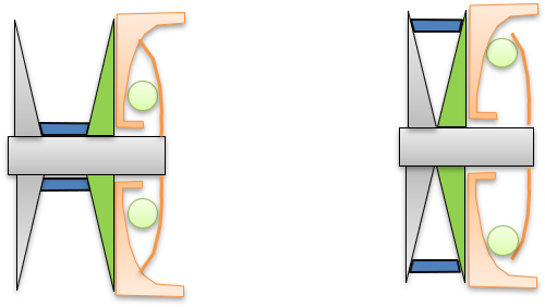
Figure 8. Roller and ramp geometry 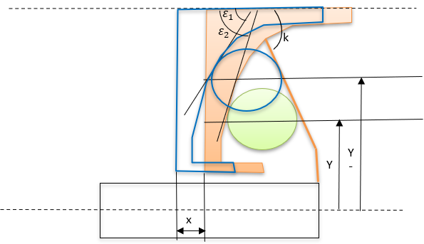
- Ramp Profile
- The curve below shows the relation between the roller distance from shaft centreline
(
 ) with axial shift of the sheave in primary pulley (
 ).
).Figure 9. 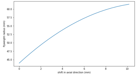 The curve below shows the relation between the ramp angle (
 ) with the axial shift of the sheave in primary pulley
().
) with the axial shift of the sheave in primary pulley
().Figure 10. 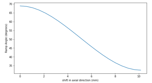
- Secondary Pulley Clamping Force:
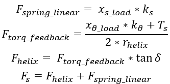
- The secondary pulley uses a torsional spring and a torque regulator cam also known
as helix cam to generate the clamping force.
Figure 11. Helix cam/Torque regulator geometry 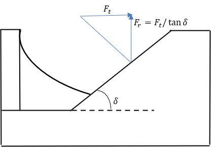
3. Shift Ratio Calculation
To calculate the shift ratio, CMM model is used. According to the CMM model, the variator belt will shift if the clamp force ratio on the primary and secondary pulley is not equal to the stationary clamp force ratio. The stationary clamp force is the ratio of clamp force at which the belt is in equilibrium and does not shift.
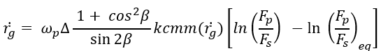
The  coefficient needs to be measured experimentally.
 is the stationary clamp force ratio.