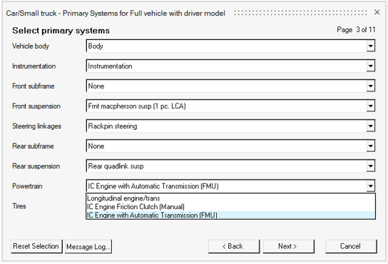
IC Engine with Automatic Transmission Powertrain
- Internal Combustion Engine (IC Engine)
- Torque Converter with a Lockup Clutch
- Gearbox
- Shift Logic
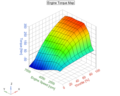
The powertrain model incorporates a 2-D Engine Torque Map to determine the torque output of an engine based on throttle input and engine speed. It also includes a torque converter with a lockup clutch which transmits the torque to the gear box and a transmission control unit to determine gear shifts and engagement of the lockup clutch.
Powertrain 1D Representation
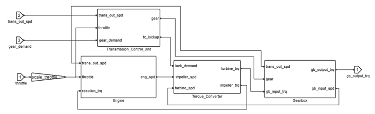
Engine Block
Throttle demand, impeller (reaction) torque and the rotational speed of the gearbox’s output shaft are the inputs to the engine, which is coupled to the transmission through the impeller of a torque converter. The output of the engine block is the rotational speed of the engine’s crankshaft.
As an approximation, it can be assumed that a spark-ignition gasoline engine (SIE) or a compression-ignition diesel engine (CIE) may be represented as a torque source with a constant inertia of rotating masses (in reality, the actual moment of inertia due to changing positions of pistons, is a variable that is smoothed by a flywheel inertia). Based on the engine control method, an appropriate torque sufficient for stable operation in a stationary mode may be represented as follows:
- is the throttle opening level
- is the engine’s crankshaft angular speed
The engine performance indicators are represented by the torque-speed characteristics, composing the engine map. The Engine block in Twin Activate consists of a two-dimensional table that interpolates engine torque based on throttle and engine speed. The differential equation for the rotation of the engine’s crankshaft is:
- is engine speed
- is the moment of inertia of both engine and impeller
- are engine (brake) and impeller (reaction) torque respectively
Additionally, an anti-stall system is applied based on the rotational speed of the gearbox’s output shaft. If the shaft speed is lower than the corresponding engine idle speed with no throttle opening and in gear, the engine is cut-off.
Torque Converter Block
In a torque converter, the impeller is connected to the output shaft of the engine and the turbine connected to the input shaft of the transmission. Slips between the two elements occur when the torque is transferred. The relationship between input and output speeds, also called Speed Ratio, describes the behavior of a fluid coupling application. A practical and common way of determining this relationship is in terms of the ratio of turbine speed (gearbox input shaft speed) divided by impeller speed (engine speed). The torque converter representation is built based on steady-state look-up tables which relate the steady-state Torque Ratio and Impeller Torque Coefficient to the Speed Ratio.
The inputs to the Torque Converter block are engine (impeller) and gearbox input shaft (turbine) speeds, and the outputs are the impeller and turbine loading moments. These moments can be expressed as:
- is the impeller torque coefficient as a function of the speed ratio between input and output shafts
- the density of the viscous fluid within the torque converter
- the torque converter maximum outer diameter
- turbine speed
- the impeller torque as a function of the speed ratio
The speed ratio between the torque converter input and output shaft is saturated between 0 and 1 to ensure simulation stays within operational range.
The efficiency of the torque converter is defined as the ratio of the turbine power ( ) to the impeller power ( ):
At stall and low speed ratios the advantage of torque amplification usually outweighs the drawback of power-loss, but as the Speed Ratio increases the torque amplification is lost, while the power-loss is persistent. This can be solved by the introduction of a lock-up clutch integrated in the turbine assembly. As the Speed Ratio gets close to 1, meaning that the turbine speed is close to the impeller speed, the friction disc lock-up clutch engages and locks the turbine to the torque converter housing. This effectively locks the impeller and turbine together eliminating the slip and the associated losses. During this mode, the Speed Ratio as well as the Torque Ratio is equal to 1.
The lockup clutch is modeled as a spring-damper capable of transferring torque from the impeller to the turbine based on the desired clutch engagement input signal. The torque produced by the clutch with the torque generated by the torque converter’s viscous fluid is applied to the gearbox input shaft.
The state of the clutch is defined using the following equation:
- is the clutch engagement torque
- is the desired engagement signal produced by the transmission control unit and passed through an appropriate delay transfer function
- is the clutch stiffness
- is the clutch damping
- is the clutch slip angle
The torque is also saturated between and (Clutch capacity) to ensure that the maximum engagement torque is not exceeded.
The desired engagement signal is dimensionless. Zero (0) desired engagement represents disengagement of the clutch, while one (1) represents engagement of the clutch and locking of the impeller and turbine shafts. The derivative of clutch slip is given by the following equation:
Transmission Control Unit Block
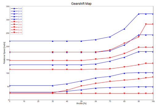
Custom timer blocks are used to establish a minimum time in gear after upshifting or downshifting, during which further upshifts or downshifts are not allowed. This correction along with appropriate transfer functions are required as no physical model of the actuation system of clutches and gears are included. An additional constraint is introduced to prevent upshifting after a sudden release of the accelerator pedal. This is achieved by monitoring the rate of change in throttle opening and blocking demanded upshifts when that rate falls below a chosen threshold.
Gearbox Block
The transmission’s gearbox is modeled as a simple algebraic input-output relation, considering the current gear ratio and the overall efficiency of the gearbox assembly. Inputs to the Gearbox block are the torque applied to the input, the rotational speed of the output shaft and the current gear. The gearbox block calculates the amount of torque at the output of the transmission and the rotational speed of the input shaft based on rotational speed of the output shaft, input torque, and current gear value, according to the following equations:
- are the torques at the input and output shafts of the gearbox
- are the rotational speeds of the input and output shafts
- the current gear ratio
- the gearbox’s efficiency
Automatic Transmission Powertrain in MotionView Vehicle Library
- Attachments
-
Label Variable Attachment Entity Comments PowerTrain Mount Body b_body Vehicle Body Differential Body b_diff Carrier Only for FWD Vehicle CG Location p_cg_location Vehicle Body CG Only for FWD - Bodies
- The following bodies are included in the system:
- Engine/Trans: It represents the lumped mass and inertia of the engine in a non-operating condition. The engine’s crankshaft and its rotation are not modeled. Instead, the lumped inertia of the crankshaft and the rigidly attached flywheel and impeller is considered within the FMU model. The engine body is attached to the vehicle body using bushing entities.
- Main Shaft (Only for RWD and AWD drivelines): Represents the transmission’s output shaft and receives the FMU’s output torques applied. Its angular speed directly corresponds to the gearbox’s output shaft rotational speed. It is connected to the Engine body by a rotational joint and through couplers to the appropriate axle in the driveline.
- Engine/Transmission Mounts
- The engine body is attached to the chassis by three bushings. The mount locations and orientations of the bushings are defined parametrically, using the corresponding points in the MDL system.
- FMU Engine and Transmission
- Contains the FMU representation of the Automatic Transmission Powertrain with
inputs, outputs, parameters, and solver settings.
- FMU Inputs
-
Connections Description Units Throttle from Driver The accelerator pedal's input from the Driver. 0 – 1 Transmission Output Speed The rotational speed of the gearbox’s output shaft. Manual Gear Demand Optional. If enabled, it allows the user to provide a gearshift history signal to the FMU through the ‘Gear Demand’ solver variable. 1 – 6 - FMU Outputs
-
Connections Description Units Transmission Speed Output Torque Engine Speed Engine Torque Current Gear 1 – 6 Lockup Status 0 – 1 Speed Ratio 0 – 1 Gearbox Input Shaft Speed TC Efficiency 0 – 1 - FMU Parameters
-
Name ID Description Units Clutch Capacity Cc The maximum torque the clutch can apply. Engine Inertia Ie Rotational Inertia of both engine and impeller bodies. Maximum Engine Torque max_net_torque The maximum torque that the engine can produce. Rated Engine Speed rated_eng_rpm The rated speed of the engine. Maximum Engine Speed max_eng_rpm The maximum angular speed of the engine’s crankshaft. Initial Engine Speed omega_ini The initial angular speed of the engine. Engine Stall Speed Ll The stall speed of the engine. Clutch Damping dc Damping coefficient of the lockup clutch’s torsion spring. Clutch Stiffness kc Stiffness coefficient of the lockup clutch’s torsion spring. Downshift Threshold ds2 – ds6 Transmission output shaft speed thresholds for downshifting at full throttle, for gears 2 – 6. Upshift Threshold us1 – us5 Transmission output shaft speed thresholds for upshifting at full throttle, for gears 1 – 5. gratios gratios Gear ratios. Gearbox Efficiency eta_gbox Gearbox Efficiency. Lockup Threshold lock3 – lock5 Transmission output shaft speed thresholds for engaging the lockup clutch at full throttle, for gears 3 – 5. Unlock Threshold unlock3 – unlock6 Transmission output shaft speed thresholds for disengaging the lockup clutch at full throttle, for gears 3 – 5. Manual Option manual Option for switching between automatic and manual gear selection. 0, 1 Minimum Time for Upshift us_wait Minimum time before accepting another upshift, after upshifting. Minimum Time for Downshifting ds_wait Minimum time before accepting another downshift, after downshifting. Throttle Scaling scale_throttle Throttle scaling coefficient. 0 - 1 Clutch Scaling clutch_torque_scale The value by which the torque converter’s lockup clutch applied torque is scaled. 0 - 1 Downshift Threshold Scaling downshift_th_scale The value by which the calculated speed threshold for downshifting is scaled. 0 - 1 Upshift Threshold Scaling upshift_th_scale The value by which the calculated speed threshold for upshifting is scaled. 0 - 1 Lockup Threshold Scaling lockup_th_scale The value by which the calculated speed threshold for engaging the torque converter’s lockup clutch is scaled. 0 - 1 Unlock Threshold Scaling unlock_th_scale The value by which the calculated speed threshold for disengaging the torque converter’s lockup clutch is scaled. 0 - 1 Minimum Throttle Opening Gradient for Tip-out correction min_throttle_grad_tipout The minimum value for throttle opening gradient, below which upshifting is blocked (tip-out correction). TC Viscous Fluid Density rho An estimate for the density of the viscous fluid coupling impeller and turbine in the torque converter. TC Diameter D Maximum outer diameter of the torque converter.
- Forces
- Differential Torque: Action-reaction torque applied to the output of the transmission. In the case of a FWD system, it is applied directly to the pinion. For RWD and AWD systems, it is applied to the main shaft body in the same system. The reaction torque is applied to Engine/Trans body.
- Solver Variables
-
Entities Type Description Comments Driver Throttle Output Attachment Solver Variable Throttle Signal from driver. 0 - 1 Dummy Driver Clutch Output Attachment Solver Variable Dummy solver variable for the driver. Dummy Driver Gear Output Attachment Solver Variable Dummy solver variable for the driver. Dummy Engine Speed Attachment Solver Variable Dummy solver variable for the driver. Gearbox Input Shaft Speed Solver Variable The rotational speed of the gearbox’s input shaft, coupled to the torque converter’s turbine. Gear Demand Solver Variable A gearshift history signal for the FMU to follow. FMU Output Torque Solver Variable The torque to be applied to the output of the transmission. Gearbox Output Shaft Speed Attachment Solver Variable Gearbox output shaft speed. Note: The expression in the ‘FMU Output Torque’ solver variable is valid only when MODEL units for length is mm. The powertrain model units are N, m, kg, s. You are responsible for changing the 1000 scaling factor if MODEL units are different. - Datasets
-
- Powertrain Data (engine, clutch)
- Contains information necessary for the Altair Driver present in a full vehicle
model.
Label Description Throttle Scaling Variation of throttle 0-1 Max Powertrain Torque Toque output from the powertrain at 100% throttle Min Powertrain Torque Toque output from the powertrain at 0% throttle Transmission Efficiency Input omega/(output omega*Gear ratio)
Limitations
- No information about the selected gear is provided to the Altair Driver. In order to provide this information, the GEAR_CLUTCH_CONTROL block inside the ADF file must be edited to include the corresponding output signal from the FMU through the User Signals tab available in the Altair Driver MDL entity.
- The engine shaft inertia of its crankshaft with rigidly linked elements, including flywheel and the impeller of the torque converter is considered within the FMU. The inertia of the rotational components of both turbine, gearbox input shaft and gearbox should be lumped together in the body that represents the output shaft of the transmission.
- Since there is no model of the actuation system of clutches and gears within the gearbox, potential spikes in the output torque signal during a gearshift may be encountered.
Editing the Twin Activate Model and Generating the Powertrain FMU
In order to modify the powertrain model characteristics, equations, controls, and logic, the Twin Activate model of the powertrain must be edited and a new FMU recreated.
- A custom engine torque map can be provided in the diagram context of the engine superblock. The references inside the eng_trq_lookup also need to be resolved.
- A custom torque converter characteristic can be provided in the diagram context of the Torque_converter superblock, resolving the corresponding array attachments in the lookup tables lamda and torque_ratio_lookup.
Once the desired changes are made, a new FMU can be exported using the Code Generation and Model Exchange options.
References
- 1. Diachuk M, Easa SM. Modeling Combined Operation of Engine and Torque Converter for Improved Vehicle Powertrain’s Complex Control. Vehicles. 2022; 4(2):501-528. https://doi.org/10.3390/vehicles4020030
- LI, Y. A. N. G.; SUNDÉN, Max. Modelling and measurement of transient torque converter characteristics. 2016. PhD Thesis. Chalmers University of Technology.
- KIRTANE, Chinmay, et al. Gear shift schedule optimization and drive line modeling for automatic transmission. In: Proc. 1st Int. 16th Natl. Conf. Mach. Mech. 2013. p. 254-260.