Part 2: Create Design Study 2
Import Geometry
The new geometry is almost identical to that of Study 1. The only difference is the design of the vertical support brackets. SimSolid instances identical geometry to minimize resources required; this makes the database smaller and the solutions faster.
-
On the main window toolbar, click Import from file
 .
.
- In the Open geometry files dialog, choose Pullup bar V2.x_t.
-
Click Open.
The new geometry is read into a second design study. All analysis definitions are copied from Study 1 to Study 2. Conflicts and inconsistencies are flagged in red in the Project Tree. This tutorial does not require you to fix geometric inconsistencies.Note: New parts in the assembly do not yet have materials assigned.
Figure 1. Design Study 1 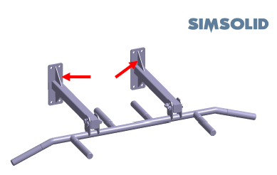
Figure 2. Design Study 2 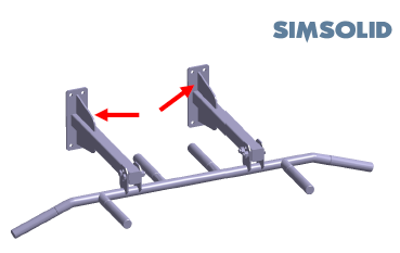
Add Connections for New Parts
- In the Add connections for new parts dialog, specify gap and penetration tolerances as 1.
- For Connection resolution, select Increased.
- Click OK.
Assign Materials
- On the Project Tree, click on the Assembly workbench.
-
On the Assembly workbench, click
 (Apply materials).
- Pick Steel from the Generic materials list.
- Click Apply to all parts.
-
Click Close.
In the Assembly branch of the Project Tree, material properties are identified for each part.
Run Design Study
Solve all analyses in the design study.
- In the Project Tree, select Design study 2 branch.
-
Click Run All Analyses
 .
.
- In the Solver Manager, verify all analyses are selected.
-
Click Solve.
SimSolid runs all analyses in the design study branch. When finished, a Results branch for each analysis appears in the Project Tree.Note: Analysis 1 runs in 11 seconds. SimSolid reuses model data structures for Analysis 2 so the analysis runs faster.
Compare Results
- In the Bookmark browser, click a thumbnail to load a saved results view.
-
In the Project Tree, click on any
Results branch.
The modeling window updates with the results from the chosen analysis. You can click on other Results branches to rapidly switch between views.
View Reaction Forces
- On the Project Tree, open the Analysis Workbench.
-
On the Analysis Workbench toolbar, click the
 (Reaction/contact force).
-
Click the Supports, Connections,
or Parts tab.
A summary table of the reactions opens. Moment vectors are displayed in the modeling window.
Figure 3. 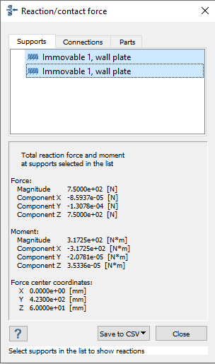
- Optional: Select a single support, connection, or part to view forces on a single element.
- Optional: Select multiple supports, connections, or parts to view a summary of forces.
Compare with Traditional FEA
-
Use the model files to run this same analysis with your traditional FEA
application.
Important:
- Do not merge or simplify geometry, use bonded and sliding contact same as SimSolid.
- Check for part overlaps
- Make sure element density is acceptable for smaller parts
-
Compare the following between the two programs:
- Solution quality
- Number of workflow steps required
- Time required to mesh
- Time required to solve
- Time required to examine results
- Time required to refine and rerun model