SS-T: 4010 Structural Non-linear Analysis
Tutorial Level: Intermediate Run structural non-linear analysis in SimSolid.
- Purpose
- SimSolid performs meshless
structural analysis that works on full featured parts and assemblies, is
tolerant of geometric imperfections, and runs in seconds to minutes. In this
tutorial, you will do the following:
- Create structural non-linear analysis (material and contact).
- Model Description
- The following files are needed for this tutorial:
- MaterialNonLinearity.ssp
- Stress_strain_curve.csv
-
Figure 1. 
Open Project
- Start a new SimSolid session.
-
On the main window toolbar, click Open Project
 .
.
- In the Open project file dialog, choose MaterialNonLinearity.ssp
- Click OK.
Define Non-linear Material
- In the main menu, click .
- In the dialog, right-click on the Sample non linear materials folder, and then select Add Material from the context menu.
- Select Add stress-strain curve....
- Click Edit.
-
Import the Stress-strain curve.
-
In the dialog, click OK.
Figure 2. 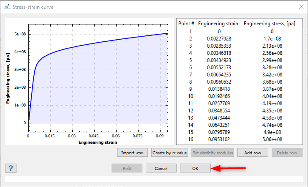
In the Edit Material database dialog, you can see the Elasticity Modulus was calculated from the imported stress-strain curve.Figure 3. 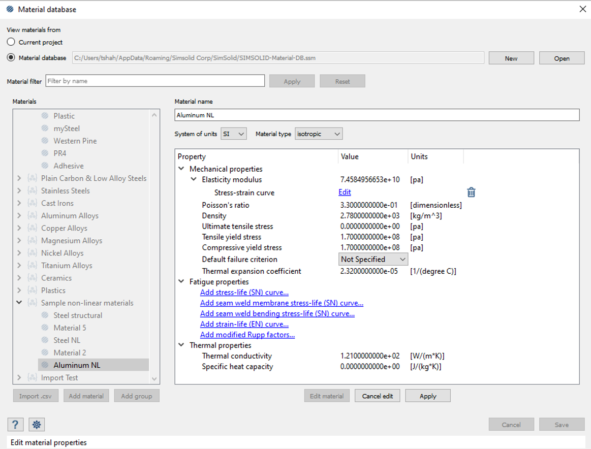
-
In the dialog, click OK.
-
Enter other values in the dialog,
- For Poisson's ratio, enter 0.33.
- For Density, enter 2.78e03.
- For thermal expansion coefficient, enter 2.32e-05.
- For Thermal conductivity, enter 1.21e02.
- Edit material name to Aluminum NL.
- Click Apply.
- Click Save.
Assign Materials
- On the Project Tree, click on the Assembly workbench.
-
Click
 (Apply material).
-
In the dialog, click
 to expand the Sample non-linear materials
folder.
to expand the Sample non-linear materials
folder.
- Pick Aluminum NL from the list.
- Click Apply to all parts.
-
Click Close.
In the Assembly branch of the Project Tree, material properties are identified for each part.
Create Structural Non-linear Analysis
-
In the main window toolbar, click
 > Structural non-linear.
- In the dialog, select the Material non-linear check box.
- Click OK.
Create Immovable Support
-
In the Analysis Workbench, click Immovable
Support
 .
.
- In the dialog, verify the Faces radio button is selected.
-
In the modeling window, select the faces highlighted in
orange in Figure 4.
Figure 4. 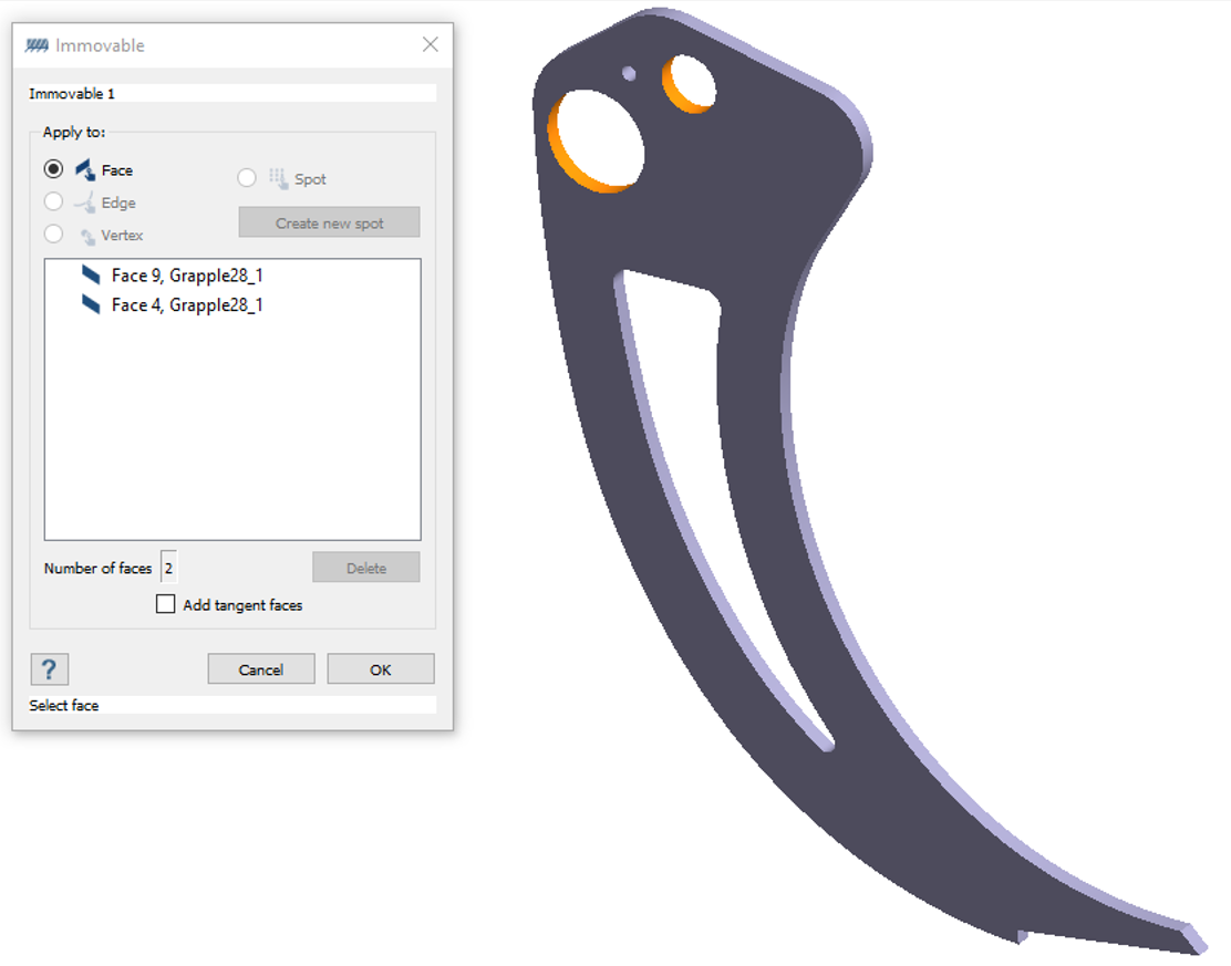
- Click OK.
Define Pressure
-
In the workbench toolbar, select
 Pressure→Uniform Pressure.
-
Select the face as shown in Figure 5.
Figure 5. 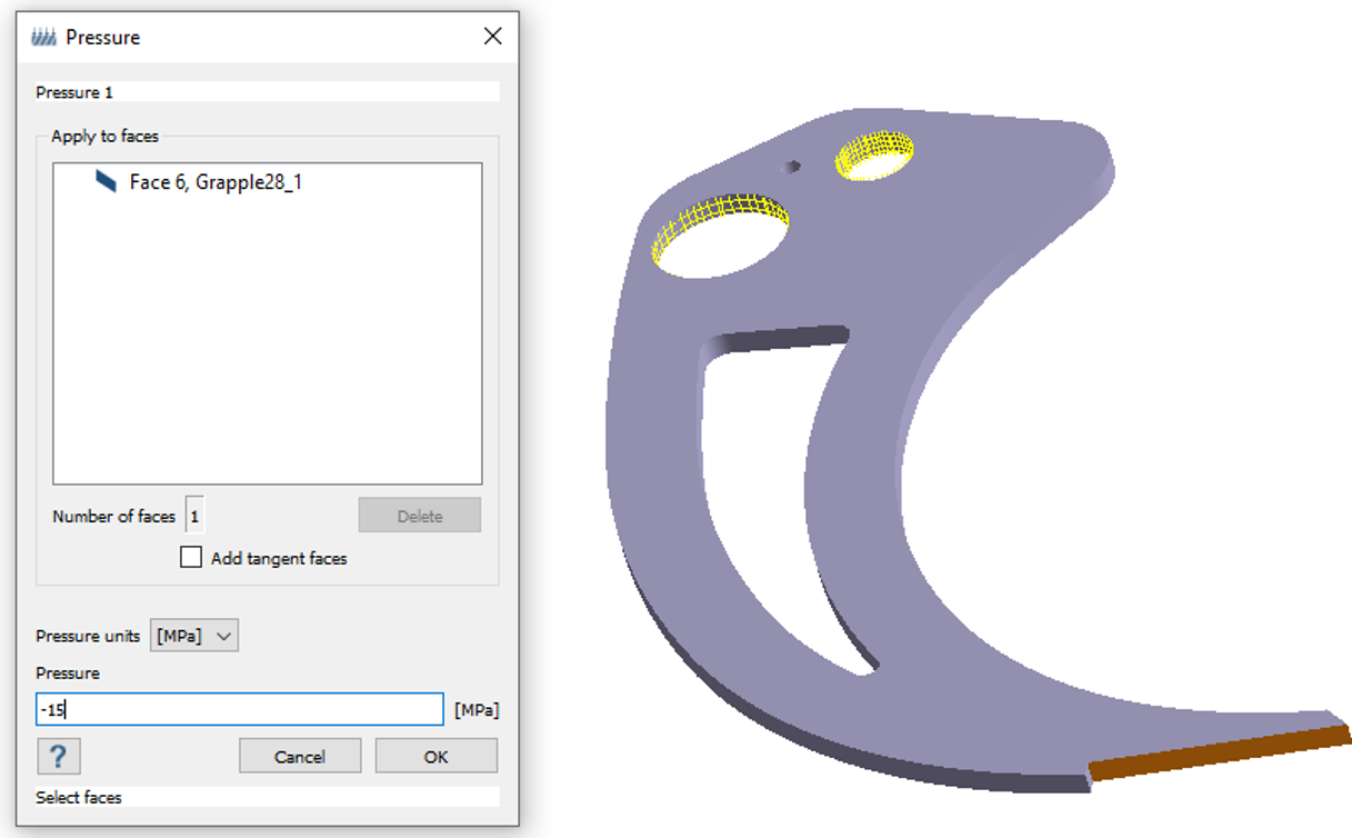
- For Pressure, enter -15 MPa.
- Click OK.
Edit Solution Settings
- In the Analysis branch of the Project Tree, double-click on Solution settings.
- In the Solution settings dialog, for Adaptation select Global+Local in the drop-down menu.
- Click OK.
Run Analysis
- On the Project Tree, open the Analysis Workbench.
-
Click
 Solve.
Review Results
-
On the Analysis Workbench
toolbar, click
 Results plot.
-
In the menu, select Displacement Magnitude.
The Legend window appears showing the contour plot. The Results window appears. You can review the plot for different zones.