SS-T: 4060 Frequency Response Analysis
Create frequency response analysis in SimSolid for a vertical wind turbine assembly.
- Purpose
- SimSolid performs meshless structural
analysis that works on full featured parts and assemblies, is tolerant of
geometric imperfections, and runs in seconds to minutes. In this tutorial,
you will do the following:
- Use modal analysis results to create a frequency response analysis.
- Model Description
- The following model file is needed for this tutorial:
- Frequency.ssp
-
Figure 1. Wind turbine model 
Open Project
- Start a new SimSolid session.
-
On the main window toolbar, click Open Project
 .
.
- In the Open project file dialog, choose Frequency.ssp
- Click OK.
Create Modal Analysis
-
On the main window toolbar, click the
 (Modal analysis) icon.
- In the popup Number of modes window, specify the number of modes as 9.
-
Click OK.
The new modal analysis appears in the Project Tree.
Create Immovable Support
-
In the Analysis Workbench, click Immovable
Support
 .
.
- In the dialog, verify the Faces radio button is selected.
-
In the modeling window, select the face highlighted in
Figure 2.
Figure 2. 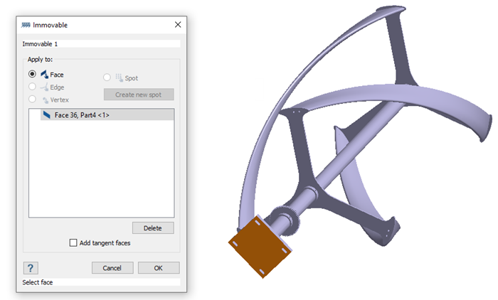
-
Click OK.
The new constraint, Immovable 1, appears in the Project Tree. A visual representation of the constraint is shown on the model.
Edit Solution Settings
- In the Analysis branch of the Project Tree, double-click on Solution settings.
- In the Solution settings dialog, for Adaptation select Global+Local in the drop-down menu.
- Click OK.
Run Analysis
- On the Project Tree, open the Analysis Workbench.
-
Click
 (Solve).
Review Modes
-
On the Analysis Workbench
toolbar, click
 (Results plot).
-
Select Displacement Magnitude.
The Legend window opens and displays the contour plot. The Frequency (Hz) window opens and displays a list of modes.
Figure 3. 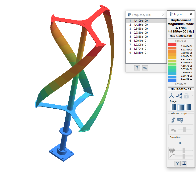
-
Review the modes.
- Select a mode in the Frequency (Hz) window.
-
In the Legend click
 to view the mode animation.
- Cycle between the different modes and view the mode shapes.
Create Frequency Response Analysis
-
On the main window toolbar, select
 > Frequency response.
The Dynamic frequency response setup dialog opens and automatically links to the Modal analysis results.
> Frequency response.
The Dynamic frequency response setup dialog opens and automatically links to the Modal analysis results. - For Frequency span, enter values for the Lower limit, 3.34, and the Upper limit, 11.59.
- Select the Modal damping tab.
- Set the Default damping ratio to 0.03.
- Click OK.
- Accept warning message.
Define Frequency Function
-
On the main window toolbar, click
 (Frequency function).
-
In the dialog, click Standard.
The Standard frequency functions dialog will open.
- Set the Function type to Uniform.
-
Click OK.
The graph and table in the Frequency function dialog populates to show the Frequency and Amplitude factor at points.
Figure 4. 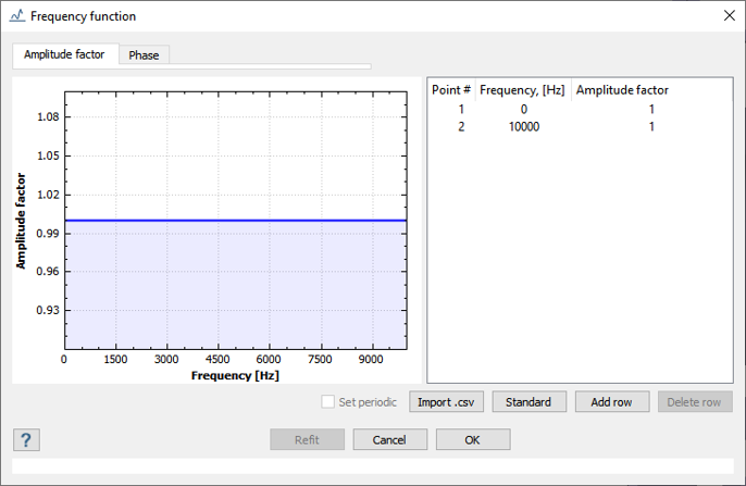
- Click OK to close the dialog.
Define Loads
-
On the Analysis Workbench toolbar, click
 (Inertia load) > Rotational inertia.
- In the dialog, activate the Apply to selected parts radio button.
-
In the modeling window, select parts as highlighted in
Figure 5.
Figure 5. 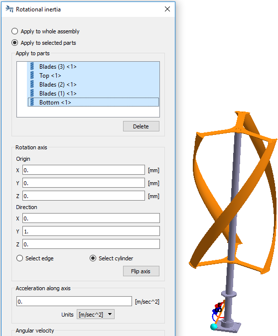
- Activate the Select Cylinder radio button.
-
In the modeling window, select the shaft as shown in
Figure 6.
Figure 6. 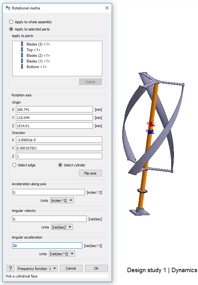
- For Angular acceleration, enter 50.
- Click OK.
Run Analysis
- On the Project Tree, open the Analysis Workbench.
-
Click (Solve).
Review Results
-
On the Analysis Workbench
toolbar, click (Results plot).
-
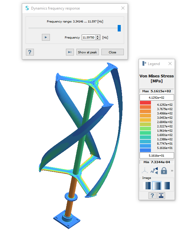
Select Von Mises Stress.
The Legend and Dynamics frequency response windows open.
Figure 7.