Some features used in this tutorial are only
available in SimSolid Advanced version. Please
switch to Advanced to complete this tutorial.
Purpose
SimSolid performs meshless structural
analysis that works on full featured parts and assemblies, is tolerant of
geometric imperfections, and runs in seconds to minutes. In this tutorial,
you will do the following:
Learn how to create a global-local analysis in SimSolid.
Model Description
The following model file is needed for this tutorial:
Wing_GlobalLocal.ssp
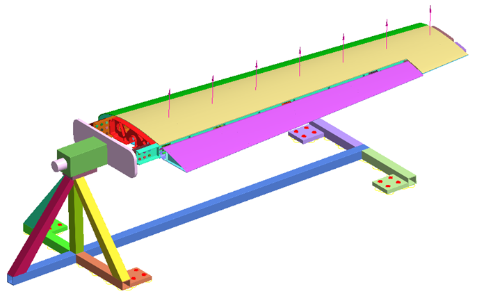
Figure 1.
The model (.ssp) file has the following
specifications:
Material is set to Aluminum and Steel for wing and fixture
assemblies.
Imported rivets.
Regular connections with 3mm gap and penetration tolerance.
Structural analysis with boundary conditions applied on the
fixture and skin.
Open Project
Start a new SimSolid session.
On the main window toolbar, click Open Project.
In the Open project file dialog, choose
Wing_GlobalLocal.ssp
Click OK.
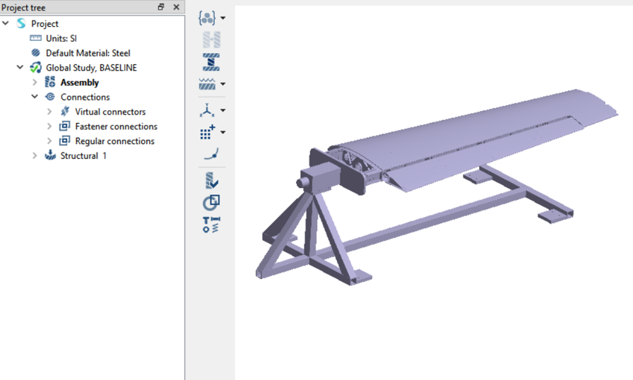
Review Model
In the Project Tree and modeling window, review the assembly, connections, and the
analysis.
Figure 2.
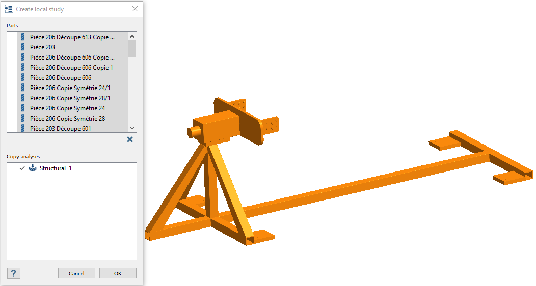
Create Local Analysis
Create a local study on the fixture.
In the Bookmark Browser, click Bookmark 1 to isolate the
fixture assembly.
In the Project Tree, select Global Study,
BASELINE to open the Design Study workbench.
Under Copy Analysis, verify Structural 1 is
selected.
This section of the dialog lists all Structural Linear and Structural
Non-linear analyses present in the current design study. All listed analyses are
selected by default.
Click OK.
The linked design study inherits all the properties, connections and
boundary conditions for the selected part from the global study. Reaction forces
from the connected parts are also mapped to the local linked analysis.Figure 4.
Note:
Any changes to material, part type, connections, analysis set up,
boundary conditions made to the global analysis are reflected in the
local analysis.
Analysis in global study should have a valid result to run the
linked local analysis.
Run Analysis
On the Project Tree, open
the Analysis Workbench.
Click (Solve).
Review Results
On the Analysis Workbench toolbar, click Result plot > Displacement > Displacement magnitude.
 .
.
 .
.
 Note:
Note: (Solve).
 > Displacement > Displacement magnitude.
 .
.
