SS-T: 4001 Buckling Linear Analysis
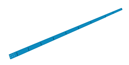
Perform buckling linear analysis on a landing gear model.
- Prerequisites
- Some features used in this tutorial are only available in SimSolid Advanced version. Please switch to Advanced to complete this tutorial.
- Purpose
- SimSolid performs meshless structural
analysis that works on full featured parts and assemblies, is tolerant of
geometric imperfections, and runs in seconds to minutes. In this tutorial,
you will do the following:
- Learn how to create buckling linear analysis in SimSolid.
- Model Description
- The following model files are needed for this tutorial:
- buckling.ssp
Open Project
- Start a new SimSolid session.
-
On the main window toolbar, click Open Project
 .
.
- In the Open project file dialog, choose buckling.ssp
- Click OK.
Create Immovable Support
-
In the Analysis Workbench, click
 Immovable Support .
- In the dialog, verify the Faces radio button is selected.
-
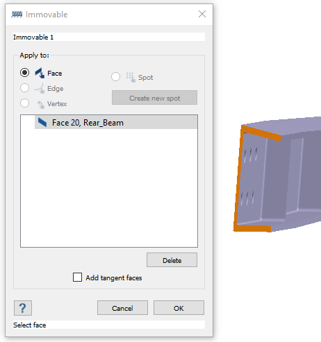
In the modeling window, select the face shown in Figure 2.
Figure 2. 
- Click OK.
Create Buckling Force
- In the Analysis Workbench, click .
- In the dialog, ensure the Faces radio button is selected.
-
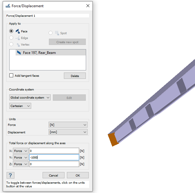
In the modeling window, select the face shown in Figure 3.
Figure 3. 
- For the Y direction Force, enter -1000 N.
- Click OK.
Create Buckling Linear Analysis
-
On the main window toolbar, click .
The new analysis (Buckling 1, linked to Structural 1) appears in the Project Tree under Design Study 1 and the Analysis Workbench opens.
- In the Buckling linear setup dialog, select Structural 1.
- For Number of modes to find, enter 6.
- Click OK.
Run Design Study
Solve all analyses in the design study.
- In the Project Tree, select Design study branch.
-
Click Run All Analyses
 .
.
- In the Solver Manager, verify all analyses are selected.
-
Click Solve.
SimSolid runs all analyses in the design study branch. When finished, a Results branch for each analysis appears in the Project Tree.
Review Results
-
Review the reusults for Design Study 1.
The results show Part 1 buckles first at a load factor of ~5.7.
-
To obtain the approximate buckling load, multiply the buckling factor by the
buckling load.
In this case, 5.7 × 1000 N = 5700 N buckling load.
