SS-T: 4045 Structural Thermal Transient Analysis
Tutorial Level: Intermediate Learn how to create a structural analysis linked to a thermal transient analysis in SimSolid.
- Purpose
- SimSolid performs meshless
structural analysis that works on full featured parts and assemblies, is
tolerant of geometric imperfections, and runs in seconds to minutes. In this
tutorial, you will do the following:
- Create a structural analysis linked to a thermal transient analysis
- Model Description
- The following model file is needed for this tutorial:
- Structual-ThermalTransient.ssp
-
Figure 1. 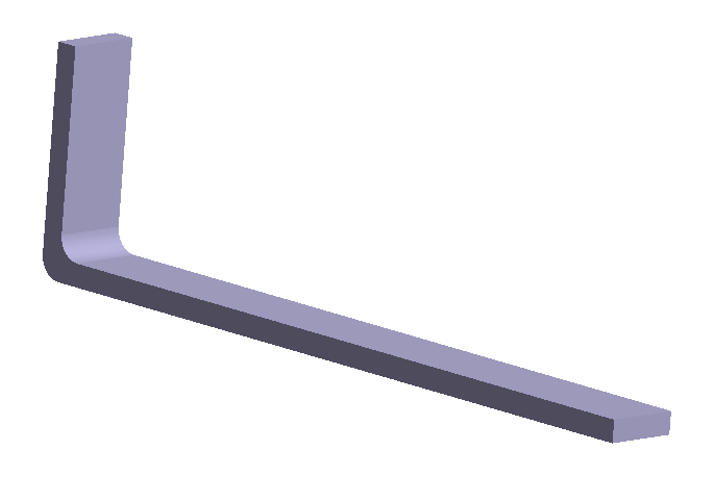
Open Project
- Start a new SimSolid session.
-
On the main window toolbar, click Open Project
 .
.
- In the Open project file dialog, choose Structural-ThermalTransient.ssp
- Click OK.
Review Model
- In the Project Tree, expand Transient thermal 1 analysis.
-
Expand the Thermal conditions branch and review the
loads.
Figure 2. 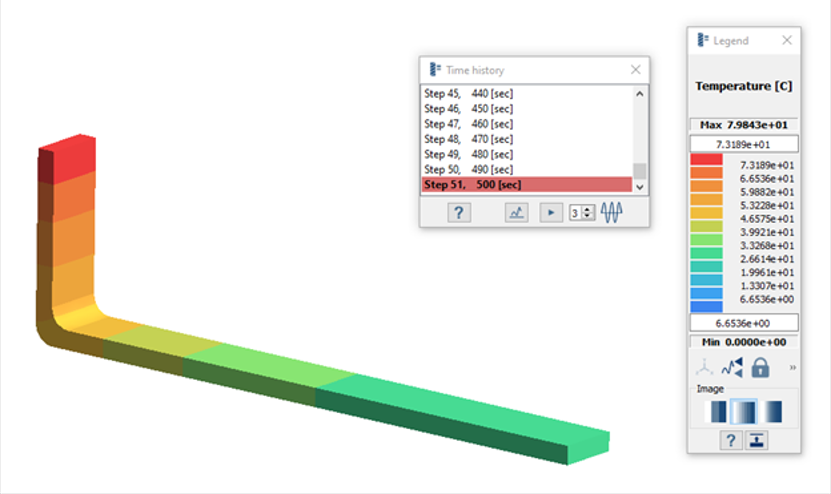
-
Click
 (Results
plot) and choose Temperature.
(Results
plot) and choose Temperature.
-
Click
 (Animate
history) to animate the time history step by step.
(Animate
history) to animate the time history step by step.
Create Transient Analysis
-
On the main window toolbar, select .
Tip: You can also right-click on an existing thermal transient analysis and select .The new analysis appears in the Project Tree.
-
In the Thermal load window, select Link to Thermal analysis
results.
Transient thermal analysis is automatically selected in the dialog.Note: If more than one analysis is present, manually choose the thermal analysis from the Thermal analysis with a result section.
Figure 3. 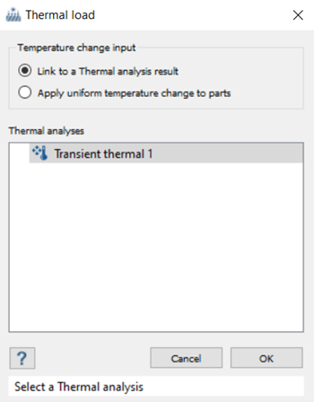
- Click OK to define the thermal load.
Create Immovable Support
-
On the Analysis Workbench, click
 Immovable support.
- In the dialog, verify the Faces radio button is selected.
-
In the modeling window, select the faces highlighted in
orange from the figure below.
Figure 4. 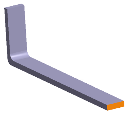
- Click OK.
Edit Solution Settings
- Double-click on Solution settings: for Structural 1.
- In the Solution settings dialog, for Adaptation select Global+Local in the drop-down menu.
- Click OK.
Run Analysis
- On the Project Tree, open the Analysis Workbench.
-
Click
 Solve.
Review Combined Result
-
On the Analysis Workbench
toolbar, click
 Results plot.
-
Select Displacement Magnitude.
The Legend and the Time History dialogs appears in the modeling window.
-
Click
 Show history graph to view a plot of the displayed
response history.
Show history graph to view a plot of the displayed
response history.
-
Click
 Animate history to animate the time history step by
step.
Tip: You can change the speed of the animation by increasing/decreasing the value in the Animation speed box.Note: Make sure the Show deformed shape function is activated when animating the history.
Animate history to animate the time history step by
step.
Tip: You can change the speed of the animation by increasing/decreasing the value in the Animation speed box.Note: Make sure the Show deformed shape function is activated when animating the history. - Close all results dialogs.
View Reactions
-
On the Analysis Workbench toolbar, click
 Reaction/contact force.
- In the Supports tab, select Immovable 1.
- For Reactions, select Force Magnitude from the drop-down menu.
-
Click Evaluate.
A plot appears showing the reaction force magnitude at Immovable 1 at each timestep.
- Optional: Click Save to save the plot as an image or the data as a text file.