SS-T: 4085 Squeak and Rattle Analysis
Create squeak and rattle analysis in SimSolid and review the status at different points along the model.
- Purpose
- Create
- Model Description
- The following model file is needed for this tutorial:
- Squeak_Rattle_Analysis.ssp
Figure 1. 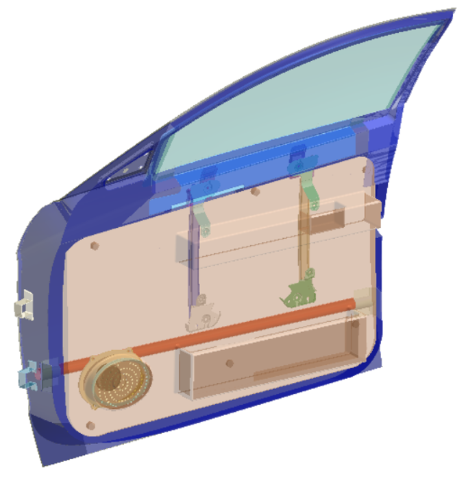
Open Project
- Start a new SimSolid session.
-
On the main window toolbar, click Open Project
 .
.
- In the Open project file dialog, choose Squeak_Rattle_Analysis.ssp
- Click OK.
Review Model
- In the Project Tree, expand Transient Dynamics2 analysis.
-
Expand the Loads&Constraints branch and review the
loads.
Figure 2. 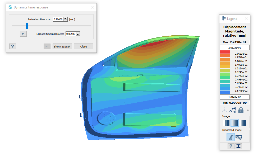
-
Click
 and
choose Displacement Magnitude.
and
choose Displacement Magnitude.
-
Click
 to view the
displacement for the time span.
to view the
displacement for the time span.
Switch to Advanced License
Skip this step is you are already using an Advanced License.
- From the top menu, go to .
- In the License Setup window, select Advanced from the Product edition dropdown.
Create Squeak and Rattle Analysis
-
On the main window toolbar, select
 > Squeak and Rattle.
The new analysis appears in the Project Tree.
> Squeak and Rattle.
The new analysis appears in the Project Tree. - In the pop-up window, select the transient analysis to link the squeak and rattle analysis with.
- Set the gap tolerances for open-close and stick-slip to zero.
Create Sampling Points
-
On the Analysis Workbench, click
 (Add/edit).
- In the dialog, select the primary and secondary components in the Primary connect tab.
-
In the modeling window, select the inner panel as the
primary part and the plastic trim as the secondary part.
Note: Any parts between the inner panel and the plastic trim can be selected as primary and secondary parts without impacting the result.
Figure 3. 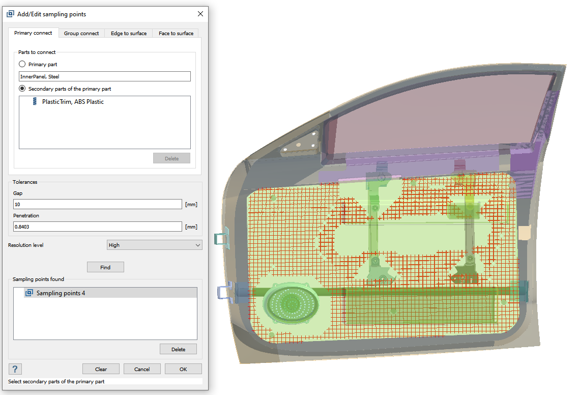
- Enter 10 for the Gap value, and keep the default Penetration value
- Set the Resolution level to High.
- Click Find.
- Review the sampling points found.
- Delete the unnecessary sampling points found at pin locations and keep only those points that can be seen in the image.
- Click OK.
Run Analysis
- On the Project Tree, open the Analysis Workbench.
-
Click
 (Solve).
Review Response
-
On the Analysis Workbench toolbar, click
 .
.
-
In the dialog, choose the sampling point and set the response type as
Final status to review the final states of various
points in the selected sampling point set.
The red points represent squeak and rattle and the green points represent no squeak and rattle.
Figure 4. 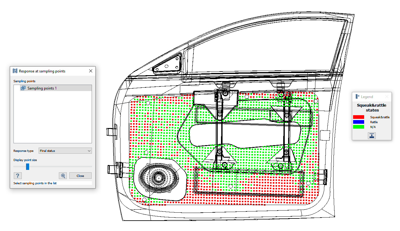
- Switch the response to Minimal gap to view the minimal normal gap due to the applied excitation.
- Select one of the points in the modeling window to view a plot for relative distance over time.