Battery_Pack
![]()
Description
- How the modules in a pack are arranged in serial and parallel
- The type of electrical input to the pack e.g. current, voltage, power or charging profile
Module arrangement:
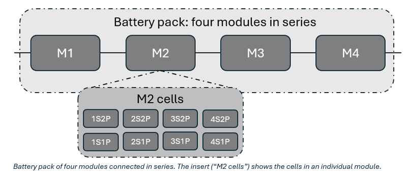
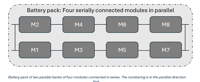
The arrangement of the modules in serial and parallel determines how the current will be distributed through the pack. These are given nSmP arrangement, where n is the number of modules in series and m is the number of modules in parallel. As an example , a pack built from four serially connected modules (e.g. 4S1P) is shown in the top figure below. An alternative pack with two parallel banks of four serially connected modules is shown in the bottom figure. Note: for consistency with the labelling at the module level, the module numbering is parallel first.Electrical input type:
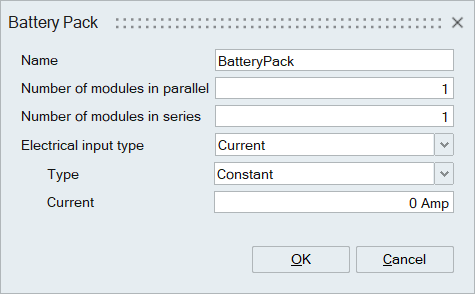
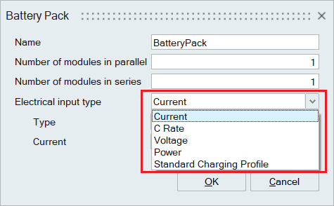
Different types of electrical input can be included as an input to the battery pack panel, as shown below. Although all inputs are done at a pack level, these are then distributed to the cell level to ensure consistency of the electrical solution. These are summarized in the following sections.
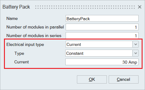
Current:
In general, when the electrical input is provided at the pack level, this is required to be distributed to the cell level based on electrical connectivity as well as individual cell properties.
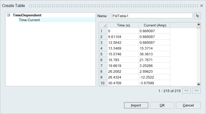
The battery solution supports both generic charging and discharging, including constant, piecewise linear, and cubic spline. Constant current discharge would be used for typical testing scenarios. Piecewise linear and cubic spline are used for experimental data, such as a driving cycle e.g. NEDC or US06. An example of a typical current input into a pack for constant current and a linear or cubic spline are shown in the figures below.
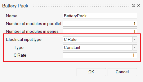
C-rate:
- Battery with capacity of 3.5Ah discharged at a c rate of 0.5C delivers 1.75A for 2 hours.
- Battery with capacity of 3.5Ah discharged at a c rate of 1C delivers 3.5A for 1 hour.
- Battery with capacity of 3.5Ah discharged at a c rate of 2C delivers 7A for 30 mins.
C-rate input is given as the c-rate value to the pack as shown below.
Constant Voltage:
Constant voltage (CV) is charging with constant voltage. The input module voltage divided by the number of parallel cells should be between the minimum and maximum cell voltage.
Power:
Power input can be provided as a constant power or a profile (piecewise linear and cubic spline). In this approach the power in the pack is calculated as the product of the pack voltage (determined from the cell and module connectivity) and the pack current at time t. Using this approach, it is possible to determine the cell current using an iterative approach based on the input power and known open circuit and polarization voltages.
Charging profiles:
Charging profiles include CC-CV (Constant Current-Constant Voltage) or CP-CV (Constant Power-Constant Voltage) methods. The voltage and current response for these charging profiles is shown in the figure below.
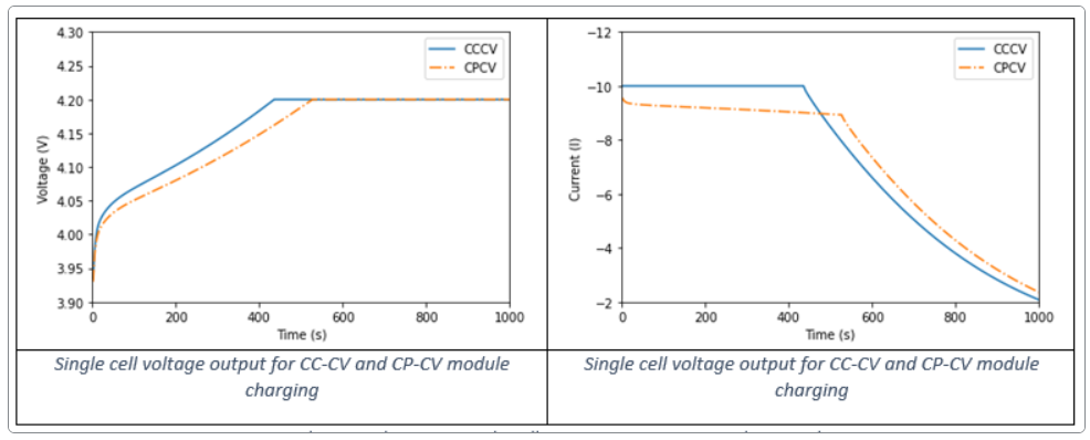
In CC-CV charging, the process begins with a constant current (or C-rate) until reaching a specified voltage limit, then switches to constant voltage charging. The simulation terminates when the current drops to a predefined level (e.g., cut off current or maximum state of charge). In SimLab this is given as a fraction of the original input current. The switch between constant current and constant voltage is defined by the maximum voltage provided on the battery specification datasheet. These data are given by the Module command.
In CP-CV charging begins by applying constant power, shifting to constant voltage once the voltage limit is reached. The termination criteria for CP-CV charging are the same as those for CC-CV.