Electric Conduction
![]()
Introduction
Battery Thermal management ensures that the battery operates at an optimal temperature range for its efficient working. High operating temperature can cause fast degradation of the battery cells thus reducing the battery life. Hence thermal analysis of battery plays a vital role in battery design and development.
- The exothermic chemical reaction generates heat in the battery cells during both charging and discharging of the battery.
- The joule heating happens in the cell as well in other electrical conducting parts like bus bars due to current flow.
SimLab provides the following workflow to compute the heat generated in the battery and simulate the thermal management of the battery pack.
Battery Thermal Management in SimLab
- Battery thermal analysis can be performed using Multi State Electric Conduction Solution with a Transient Heat Transfer Loadcase.
- SimLab uses an Equivalent Circuit Model (ECM) to mathematically model the electro-thermal behaviour of Battery cells.
- A multi-steady state electrical analysis (MSEC) is conducted to measure the joule heating effect in bus bars, terminals, and other electrical conducting parts.
- A transient heat transfer analysis is then performed by considering joule heating from the electrical analysis. The heat generated in the battery cells is calculated in transient heat transfer analysis using ECM.
- From the above two analysis, temperature distribution of battery pack can be computed during a charging/discharging cycle and the battery thermal management system can be designed based on it.
Equivalent Circuit Model (ECM):
ECM represents the electrical behaviour of the battery cell in terms of voltage, current, resistances, and capacitances. Each battery cell is modelled as an ECM.
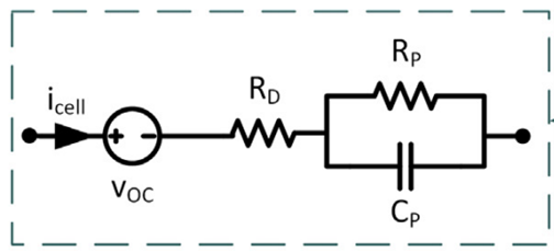
- Charging/Discharging current profile (icell)
- Open circuit voltage (VOC)
- Internal cell resistance (RD)
- Polarized cell resistance (RP)
- Polarized cell capacitance (CP)
All the above parameters vary as a function of both SOC (State of Charge) and temperature. The above parameters in the ECM model are used in the Bernardi equation to calculate the ohmic heat generation (due to joule heating effect) and entropic volumetric heat generation (due to electrochemical reaction in battery cells).
The heat generated in a battery cell is given by:
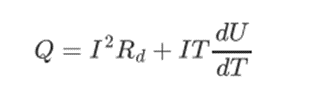
dU/dT, corresponds to the variation of the open circuit voltage with respect to temperature.
Workflow in SimLab
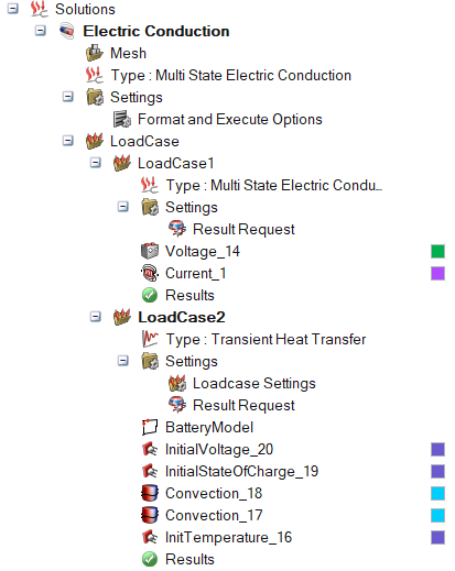
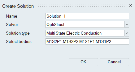
- Create an Multi State Electric Conduction solution by using Solution >
Battery > Electric Conduction
- In the solution browser right click on the Electric Conduction solution and select “Define using loadcase” option
- Create a Multi-Steady State Electric Conduction analysis as a first loadcase.
- Define the electrical boundary conditions and charging/discharging current profile
- Create a Transient Heat Transfer analysis as a second loadcase and include
Joule heating effect from the electrical analysis
- (Loadcase Settings > Include temperature Loadcase > Select the Multi-Steady State Electric Conduction loadcase)
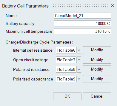
- Create a Battery model from Analysis >Battery > Battery Model and define the input parameters.
Battery Model
Battery model can be used to define the parameters required to construct an ECM. The Electric conduction workflow in SimLab currently supports first order ECM to model the battery cells.
Please use the following link for a detailed explanation on Battery Model.
- Bodies corresponding to battery cells must be named in M#S#P# format. E.g.:
M1S1P2, represents cell in the 1st Module, 1st Series, and 2nd Parallel
connection
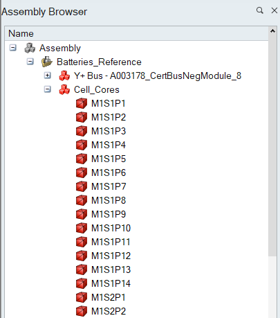
- Cell Ordering tool under Analysis > Classify Parts can be used to rename the battery cell in the required format
- Currently this renaming feature is supported only for cells arranged in rectangular pattern
- Electrical resistivity of the material assigned to battery cell bodies should be very low values (e.g., 1e−12ohm m) to avoid duplicate joule heating in the cells
Points to remember:
- Naming of the battery cell bodies in the prescribed format is mandatory to identify the cell bodies
- Electrical resistivity of the material assigned to battery cell bodies should be very low values (e.g., 1e−12ohm m), to avoid duplicate joule heating in the cells
- Any unit system can be used to model the Battery thermal problem, but it will be solved in MKS unit system only
- Along with the H3D file, a few more output files (with extension hwascii, csv and txt) will be generated while solving the battery thermal problem
- The generated output files will be placed next to the H3D file in the results
folder (Results > Right click > Open Results Folder). These output files contain
data such as:
- Heat generated in each cell at various time step
- Maximum temperature of the cells at various time step
- The ECM parameters computed at various time step