Create Synchronous Machine with Permanent Magnet

Introduction
The Create SMPM (Synchronous Machine with Permanent Magnet) Functionality enables effortless creation of motor designs compatible with electromagnetic simulations in the Flux Solver. Within a few clicks, rotor and stator configurations can be specified, along with other structural dimensions.
Dialog box
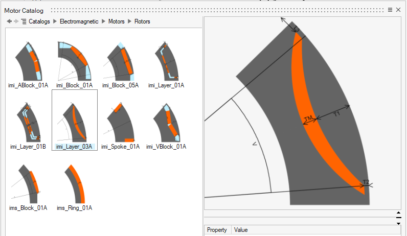
Selection of Rotor and Stator from Motor Catalog
- Navigate to the Motor Catalog within the Create SMPM functionality
- Choose suitable rotor and stator parts
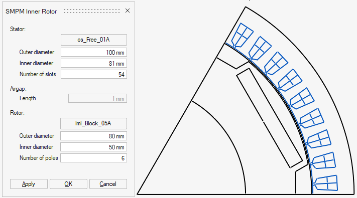
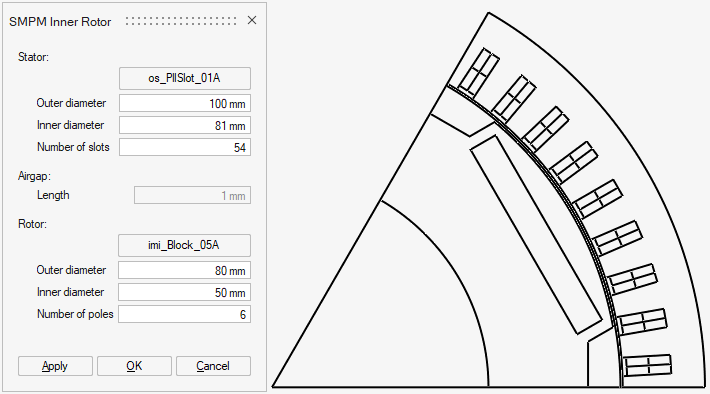
Definition of Structural Dimensions
After rotor and stator selection, the necessary structural quantities for the motor's architecture can be entered
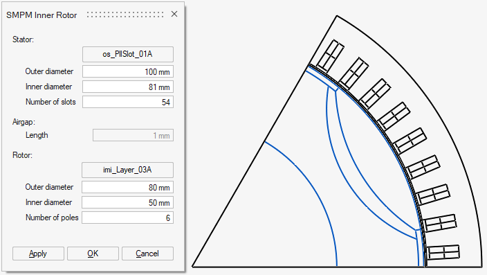
Auto-Generated Parameterized Sketches
The tool automatically generates parametrized sketches that outline the basic sector essential for electromagnetic analysis. A line in the sketch identifies the midpoint of the airgap, essential for defining mechanical sets.
- Upon sketch generation, parameter values can be fine-tuned
- Variable Manager within the sketcher interface can be employed to modify internal parameters of individual parts
- Dialog Reopen Issue: In the current version, once the dialog is closed, it cannot be reopened. To make changes to the structural data, all three sketches must be deleted, and the setup process must be initiated an.ew
Steps
- Choose the Electromagnetic solution
(Transient Magnetic solution or Magnetostatic solution)
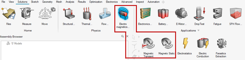
- Select the Create SMPM function
The Create SMPM function can be found in the Geometry ribbon.
→ Once the function is selected, a default SMPM sketch will be created, and a dialog box will appear allowing to adjust the sketch
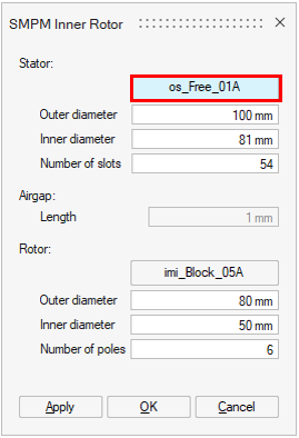
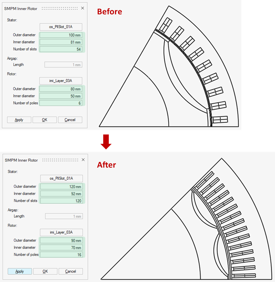
- Adjust the SMPM sketch using the SMPM Inner Rotor dialog box
The following steps can be performed in any order.
- Pick a new part for the Stator
By clicking the dedicated button for Stator changing, the Motor Catalog for SMPM Stator will appear.
From there right click on the desired part and select import.
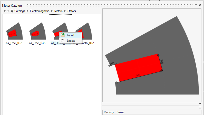
You can also locate where the part is stored by choosing Locate.
Click Apply, the SMPM sketch will be updated with the new type of stator.
- Pick a new part for the Rotor
By clicking the dedicated button for Rotor changing, the Motor Catalog for SMPM Stator will appear.
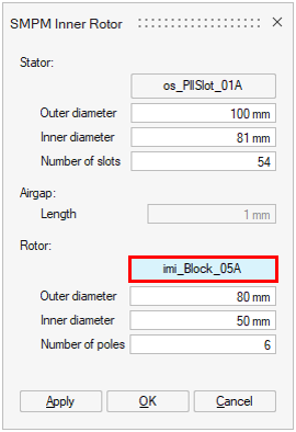
From there right click on the desired part and select import.
You can also locate where the part is stored by choosing Locate.
Click Apply, the SMPM sketch will be updated with the new type of rotor.
- Modify the structural dimensions of the
motor
The structural dimensions can be modified in any order. After the apply button is clicked, the new basic sector of the SMPM motor will be updated. The symmetry and periodicity are considered to determine the basic sector of the motor. Hence, the number of poles and slots represented can be varied according to the input dimensions.
- Click OK and the sketch is ready to be
used
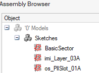
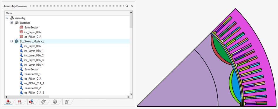
Three new sketches will appear in the Assembly browser
- The BasicSector handles the envelope of the motor sketch
- The other two sketches correspond to the Rotor and Stator parts selected in the previous steps
- Pick a new part for the Stator
- Adjust internal parameters of the motorWarning: in the actual version, please note that only the parameters with the suffix _user should be modified.
The provided parts in the Motor Catalog are parametrized in such a way that they can be automatically adapted to any changing of the structural dimensions found in the SMPM Inner Rotor dialog box. For this reason, there exist in the Variable Manager parameters serving that purpose which can be considered redundant from the point of view of end users. In the next versions, these parameters will be hidden so that users can focus on the important parameters
- Open the Variable Manager
Click the Variable button in the Sketch environment, then the Variable Manager will appear.
Click twice the Comments line to sort parameters in an intended direction.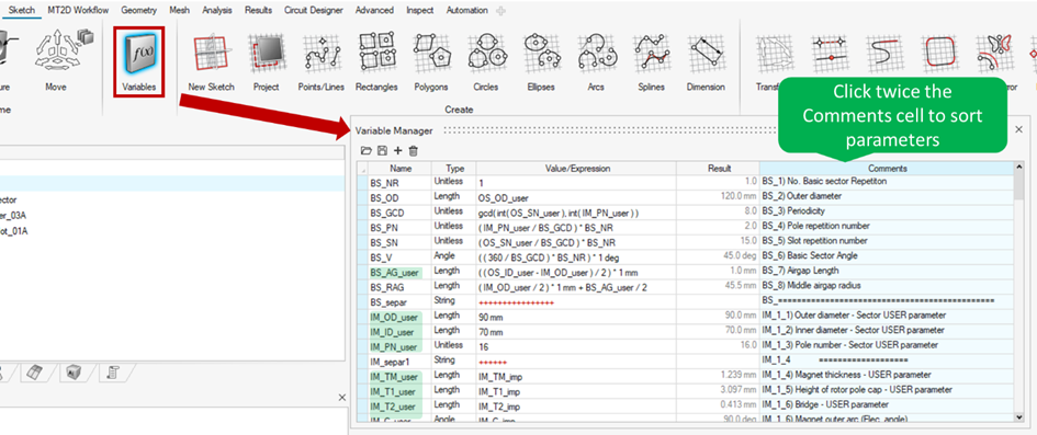
- Modify the _user parameters to update the motor
geometry
The parameters are named with a convention. It can be summarized as follows:
- Prefix states which sketch a parameter belongs to
- BS: Basic Sector (BasicSector), this sketch does not have any parameters to be modified
- IM: Inner Magnet for the SMPM Rotor sketch
- OS: Outer Slot for the SMPM Stator sketch
- Suffix states which parameters should be modified to update the
motor geometry
-
_user: only modify this type of parameters.
-
When a parameter is modified, the motor sketch is updated immediately.
Warning: For _user parameters, to perform DEO study on _user parameters containing formula in Value/Expression field, the formula must be replaced by numerical value. - Prefix states which sketch a parameter belongs to
- Open the Variable Manager
- Realize bodies
A dedicated Realize bodies function is provided for the motor sketch created by Create SMPM function.
Click right and choose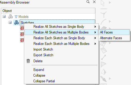
Each element of the motor is assigned a separate body as follows.
-
Play with the MT3D / MS3D Workflow
From here, the motor is ready to be meshed and electromagnetic solutions can be defined and solved. The DOE study can also be applied for this type of sketch created by Create SMPM function.
Note: In the actual version, the Number of slots OS_SN_user and Number of poles IM_PN_user are not playable in DOE study as they change the number of bodies .