Initialization by a FE Solution
Initialization
It is possible to initialize a transient magnetic solution with one of the 3
following types:
- With zero. The option is available in Solver Settings.
- With static computation. The option is available in Solver Settings.
- With a Finite Element (FE) solution. This option is detailed in this page.
Use Case and Interest
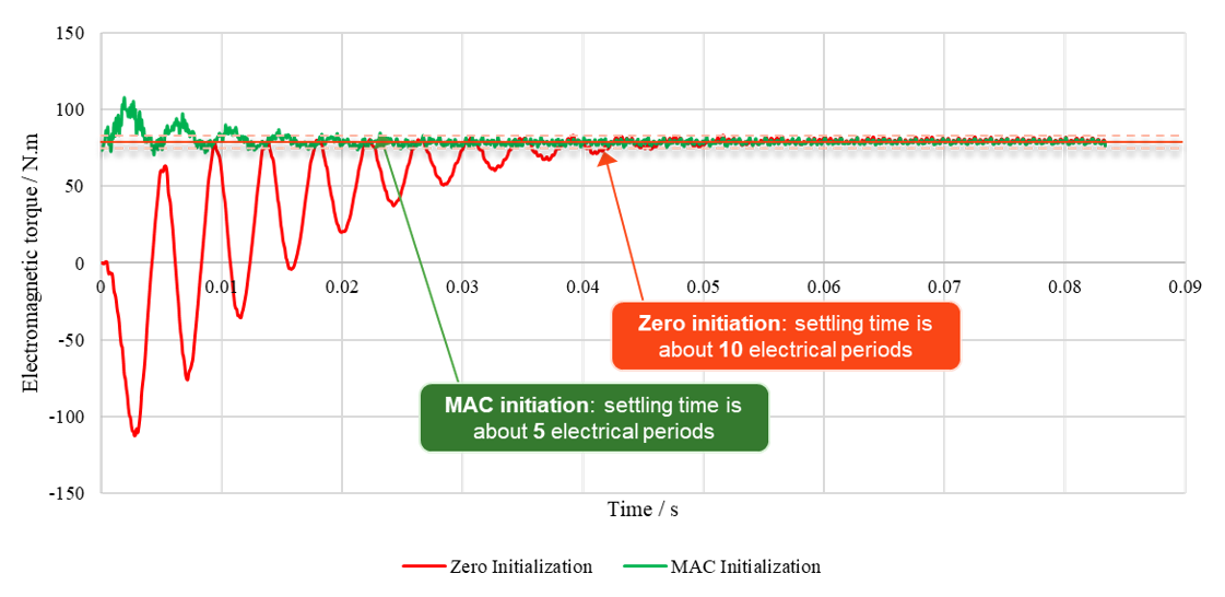
A typical use case for the Initialization by a FE solution is the induction motor analysis which takes a long simulation time to reach the steady state.
In this use case, it is possible to use either Initialization with zero or by a FE solution.
The initialization by a FE solution allows the simulation to reach the steady state more quickly than the initialization with zero.
Available Solutions
The available solutions for an Initialization by a Finite Element
solution are:
- Initialization of a 2D Transient Magnetic solution by a 2D AC Magnetic solution
Step by Step
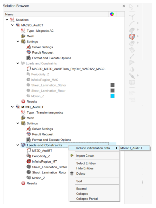
Here is an example of the Initialization by a FE solution in a MT2D solution from a MAC2D solution:
The steps to define an Initialization by a FE solution on this
example are:
- Both MAC2D and MT2D solutions must be in the same model as in the
screenshot above.Note: The MAC2D solution is not necessarily solved.
- In the MT2D solution, right-click on as in the screenshot above.
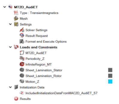
- A new node Initialization Data appears
under Loads and Constraints. It contains
a new Initialization Data
entity.
- A new node Initialization Data appears
under Loads and Constraints. It contains
a new Initialization Data
entity.
- Solve the MT2D solution.
- If the MAC2D solution is not solved, the solving will run. Then, the MT2D solution will be solved with the initialization by the MAC2D solution.
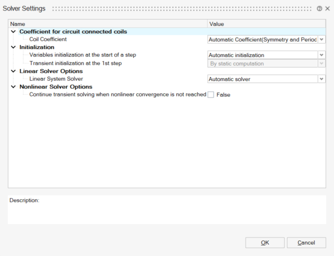
Note: When the Initialization by a FE
solution is applied, the Transient initialization at
the 1st step option in the Solver
Settings (with zero or by static computation) is greyed and ignored:
Constraints
To use the Initialization by a FE solution, the two solutions must be strictly identical.
Prerequisite: Both solutions must be in the same model.
- Same bodies must be assigned to both solutions (to guarantee the same geometry, the same mesh, the same bodies names)
- The Loads and Constraints list must be the same in both solutions,
with the same definition and the same nameNote: For the initialization with a MAC solution, as magnets are prohibited in MAC solutions, the MT solution should not contain any magnets.
- The material list must be the same in both solutions, with the same definition and the same name
- The circuit components must be the same, with the same definition and
the same nameNote: In the circuit, when using the initialization with a FE solution, an initial circuit is solved. The initial values of this circuit are determined by the solution that was used for the initialization. The coil conductors type components have initial current and thus at t=0 they are considered as current sources. Then, if for example a high value resistor is in parallel with a coil conductor, the initial current of the coil conductor component is forced to pass through this high value resistor generating a high voltage. This voltage is considered in the next step of the time resolution producing a false transient response.
Limitations
The limitations on the Initialization by a FE solution are
listed:
- For an initialization using a MAC solution: in the transient solution, the current or voltage sources must be defined as sinus signal (not as cosinus signal)
- There is not yet any automatic solution conversion (for example from MAC2D to MT2D). It is needed to define manually the solution with its physics (Loads and Constraints, circuit etc.)