Result Request

Introduction
The Result Request function has been added for AC Supplied Conductors solution. It allows the user to define the set of outputs for his study. By default, the outputs are the magnitude and phase of the electrical current and voltage on all the circuit components.
Dialog Box
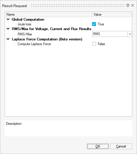
The Result Request dialog box for AC Supplied Conductors is the following:
List of Result Request for AC Supplied Conductors solution
| Result request | SimLab Solution | |
|---|---|---|
| SCAC | ||
| Global Computation | Joule loss | |
| RMS or Max for Voltage, Current and Flux | ||
| Laplace Force computation | ||
Global Computation
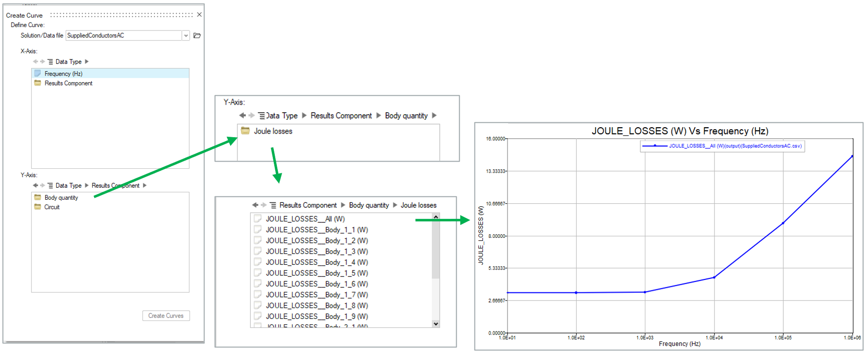
Joule lossBy default, Joule loss calculation is enabled (True). The calculated values can be seen in the 2D Plot. They are listed by Joule losses on each FEM body and also by the sum over the entire 3D structure.
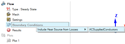
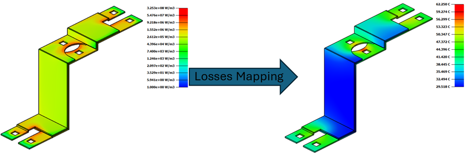
The results of Joule Losses can be mapped to Flow solution by browser right click on Boundary Conditions as follow
RMS/Max for Voltage, Current and Flux Results
The RMS/Max option allows to select the type of output for curve and contour/vector results.
If RMS is selected:
- The Currents and Voltages of the passive and active components will be in
RMS format and their flag will be named as
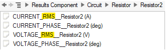
- The contour/vector results for J, V and B quantities will be in RMS values as well
If Max is selected:
- The Currents and Voltages of the passive and active components will be in
Max format and their flag will be named as
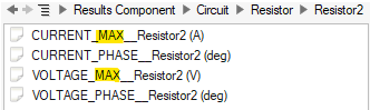
- The contour/vector results for J, V and B quantities will be in Max values as well
Laplace Force computation
- Compute Laplace Force
Enabling this option allows calculating the average and pulsating components of the Laplace force.
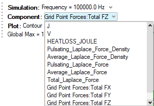
The results obtained are:
- Pulsating_Laplace_Force_Density: the pulsating
force density per mesh element in N/m3. It is a complex
number, so the phase can be changed using the according tool

- Average_Laplace_Force_Density: the average force density per mesh element in N/m3. It is a real number.
- Pulsating_Laplace_Force: the pulsating force per
mesh node in N. It is a complex number, so the phase can be changed
using the according tool
- Average_Laplace_Force: the average force per mesh node in N. It is a real number.
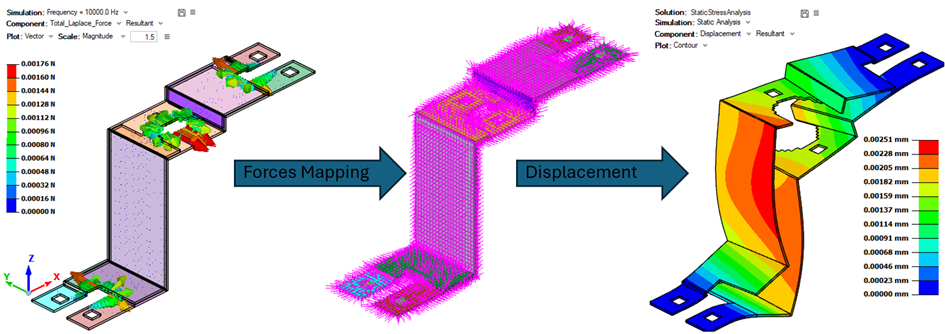
- Total_Laplace_Force: is the sum of the average
and the pulsating force per mesh node in N. It is a real number.
It is computed using this equation for each X, Y, Z component:

This total force can represent the maximum force that a three-phase system can receive in the event of a short circuit for example.
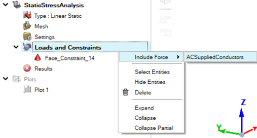
- Grid_Point_Forces: are the X, Y and Z component
of the Total forces at the mesh node in N. They are used to do the
mapping to OptiStruct solver through
Static Stress Analysis by browser right click
on Boundary Conditions as follow:
 Attention: Currently, only results from one frequency can be mapped. In the case of a multi-frequency scenario, the mapped forces are obtained from the forces calculated at the last frequency.
- Pulsating_Laplace_Force_Density: the pulsating
force density per mesh element in N/m3. It is a complex
number, so the phase can be changed using the according tool