Change Layers
![]()
Introduction
This is used to change the number of layers of elements present in features (cylinder, cone, etc.,). The options available are explained below.
Cylinder, cone and hollow disc faces
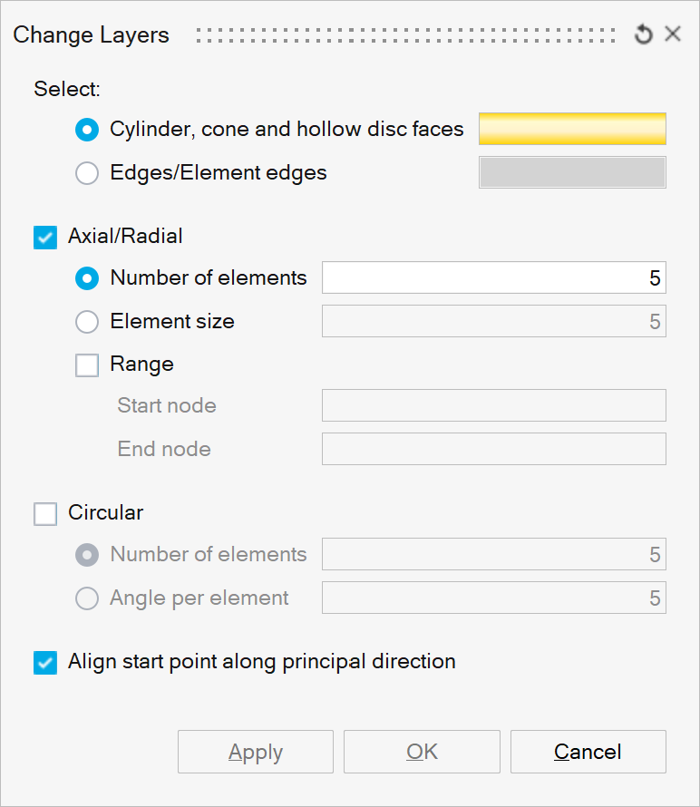
This option is used to change the number of layers of elements along the axial and circular direction for cylinder, cone, disc and hollow disc faces. User can also select the bolt-hole and change the layer.
Axial/Radial
The layer along the axial direction can be changed using this option. In case of disc/hollow disc face, the layer along the radial direction will be changed.
Number of elements
This specifies the desired number of layers along the axial/radial direction.
Element size
This specifies the mesh size along the axial/radial direction
Range
This option is used when the number of layers of elements has to be changed in a portion of the cylinder. The Start node and the End node is used to define the portion of the cylinder.
Circular
The layer along the circular direction can be changed using this option.
Number of elements
This specifies the desired number of layers along the circular direction.
Angle per element
This refers to the angle subtended by a circular spanning element edge from the axis. If the angle is 15deg, the circular division will be 24.
Align start point along principal direction
Circular mesh seeding will start from the primary direction in order to orient the scribe lines of cylinder and cone faces. Refer the following link for logic used in finding the start point for change layers. Align scribes to primary axis
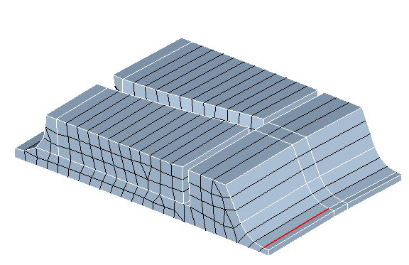
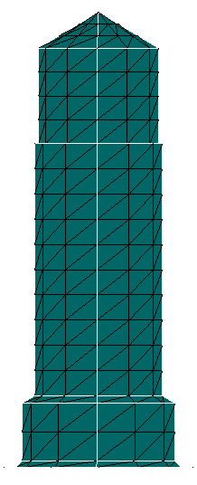
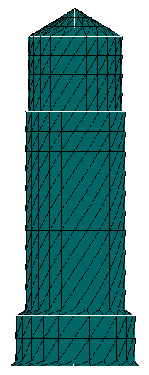
Example: Axial/Radial = ON, Circular = OFF
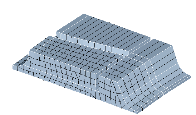
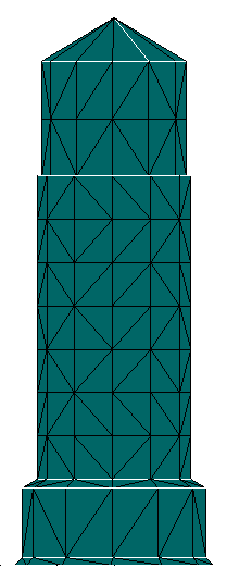
Example: Axial/Radial = OFF, Circular = ON
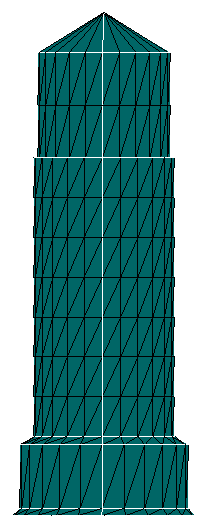
Example: Axial/Radial = ON, Circular = ON
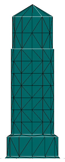
Example: Axial/Radial = ON, Range = ON, Circular = OFF
Element edge/ Edge
This option is used to change the number of layers of elements in iso-meshed faces. The number of layers of elements can be changed by selecting the element edges or edges along the faces that needs to be modified. This is supported for faces containing TRI and QUAD elements.
The options available are briefed below.
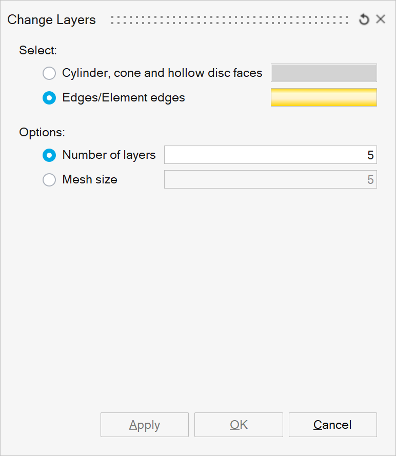
This option enables changing the number of layers of elements in a portion of the iso-meshed faces. The input is the element edges or topological edges from an iso-meshed faces. Even if the input is not continuous, each connected groupings will get modified for the given number of layers. The user can specify the desired number of layers of elements, using one of the following options.
- Number of layers
Number of layers specifies the desired number of layers of elements along the iso-mesh face.
- Mesh size
Specifies the required mesh size along the iso-mesh face.
- Node
This option is supported only for 2.5D volume meshed bodies. When this option is used, layers of elements will be created based on the selected nodes.
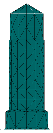
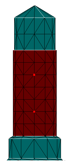
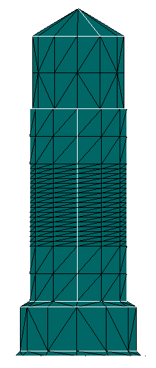
- Example: Advanced - Element edge/ Edge - Number of layers
Changing the number of layers from 1 to 5.