Surface Local Re-mesh
![]()
Introduction
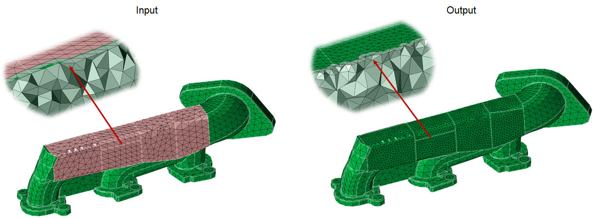
Re-mesh helps the user to re-mesh a portion of a meshed body. This comes in handy when the user wants to modify the mesh only in few places and retain the mesh elsewhere. One more advantage is that Re-Mesh respects the local mesh controls. This means that, new local mesh controls can also be assigned prior to Local Re-mesh.
Mesh faces (shared or non-shared faces), mesh edges and set of 2-D elements can be locally modified. User can give faces, edges and elements from solid body also. In case of assembled mesh bodies, the shared faces and shared edges can be re-meshed.
The global parameters to re-mesh selected faces with 2-D elements (TRI / QUAD) is specified using the Re-Mesh dialog box. The 2-D element types supported are,
- Tri3
- Tri6
- Quad4
Tri Mesh Parameters
The parameters to create Tri3 and Tri6 mesh are,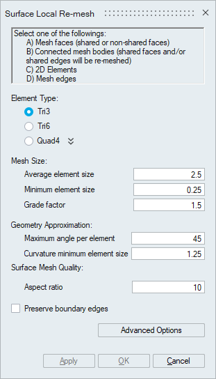
Element Type
This option can be used to create a Tri3 or Tri6 mesh.
Mesh Size
- Average element size
The Average element size is the average element edge length for Tri/Quad elements. The element edge length will vary between (Average element size)*Sqrt(2) and (Average element size)/Sqrt(2).
- Minimum element size
The Minimum element size is used to remove all the elements that have element edges less than this value.
- Grade factor
The mesh size transition on a surface mesh is controlled by Grade factor. Default Grade factor value is 1.5. (Average element size marches 1.5 times from fine to coarse).
Geometry Approximation
In case of curved surfaces/curves, the curvature is captured based on Maximum angle per element and Minimum element size along the curvature direction. By varying the Maximum angle per element and Minimum element size, the desired geometry approximation can be attained.
The default Maximum angle per element is 45 degrees. This will create 8 elements on a circular hole. A better approximation of the surface can be obtained by using a smaller Maximum angle per element. If the Maximum angle per element is reduced to 30 degrees, 12 elements will be created on a circular hole. For a very small hole the Maximum angle per element will create tiny elements and might not be desired. The creation of tiny elements can be prevented by setting the Minimum element size. The geometry will be approximated using the angle as long as the resulting element edges are greater than the Minimum element size. Otherwise, the Minimum element size will be used to define the mesh size.
Aspect ratio
The quality of mesh can be controlled by setting the Aspect ratio. The value can vary from 1 (equilateral element) to infinity (straight line). The default Aspect ratio is set to 10.
Preserve boundary edges
- Preserve boundary edges option instructs the mesher to preserve the nodes along the boundary edges. Boundary edges, here, refers to edges that are common to the faces to be re-meshed, and the faces that are not selected for re-mesh.
- When this toggle is selected the common edges will be preserved. When this toggle is not selected, in addition to the selected faces to be re-mesh, one more layer of faces will be re-meshed. Free Edges will be re-meshed in either cases, because, it does not comes under the list of common edges between the faces to be re-meshed and the faces that are not re-meshed.
Tri Mesh Advanced Options
The less often used controls are available in Advanced Options.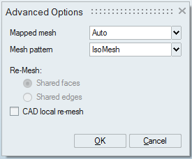
Mapped mesh
- Auto: The mesher will automatically determine the faces that can be iso-meshed. All regular 4-edged faces and faces that are 4-sided will be iso-meshed.
- Regular 4-sided faces: All regular 4-edged faces, even if the edges are not of similar size will be iso-meshed. Though a mapped mesh is created, the quality can be poor. There is no transition when a surface tapers or enlarges.
- None: Free mesh (the interior angles are 60-60-60 degrees and not 90-45-45) will be forced for all faces in the body, even if it is a regular 4 edged face.
Mesh pattern defines the pattern on faces that are mapped meshed.
- IsoMesh: IsoMesh option creates elements that are right angled and the edges of adjacent elements are inclined in the same direction.
- Union jack: Union Jack option creates elements that are right angled but the edges of adjacent elements are inclined in the opposite direction.
The iso mesh is done by default on the cylinders and 4sided faces on a FE Body.
Re-Mesh Shared facesRe-Mesh Shared faces option is used to re-mesh the shared faces in the assembled bodies.
After assembling the FE bodies (using Assembly | Connect | Join), it becomes necessary to re-mesh the affected shared faces. This option comes in handy when all the shared faces in the assembled FE Bodies are to be re-meshed. This can also be used in automation.
In addition to the shared faces, one layer of adjacent faces will also be re-meshed to cleanup the bad quality elements (along the shared edges and also in the vicinity of the shared edges) as well as to grade the mesh from fine to coarse, if the mesh size desired in the shared face is fine. The mesh in the adjacent faces will be modified only to a certain layer of elements decided by the mesher.
Re-Mesh Shared edges
Re-Mesh Shared edges option is used to re-mesh the shared edges in the assembled bodies.
This option is used to re-mesh all the shared edges. Here, three layers of elements in the faces adjacent to edges will be re-meshed.
CAD local re-meshRe-mesh on faces is done on CAD, when CAD Local remesh option is selected in Advance Options. When CAD model is present, selected face is searched in CAD body and meshing is done on CAD body. Then the meshed face is stitched to the existing mesh.
Local re-mesh on solid bodiesLocal re-mesh on faces (non-shared faces) / edges / 2D elements from solid bodies containing Tet (TET4/TET10) elements can be done. The number of tet layers that have to be modified is controlled using the option Number of Tet-Element layers considered during local mesh modification available under File | preference | mesh. By default, 3 Tet layers will be modified.
- When elements are selected for local re-mesh, only the selected elements will gets re-meshed. All other elements remains as such without any modifications.
- When re-meshing edges, three layers of elements will be modified.
Quad Mesh Parameters
SL quadThe parameters to create a Quad4 mesh can be defined. In Quad mesh, the Min Element Size is set as 1/4th of the Average Element Size. However, this can be modified to suit the requirement.
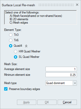
- Mesh Type
- Mixed: Generates Quad mesh with Tris as transition elements.
- Quad dominant: Generates Quad mesh with Quads as transition elements, (wherever possible).
HM quad works based on the Size and Bias or Edge deviation method of Hyper Mesh.
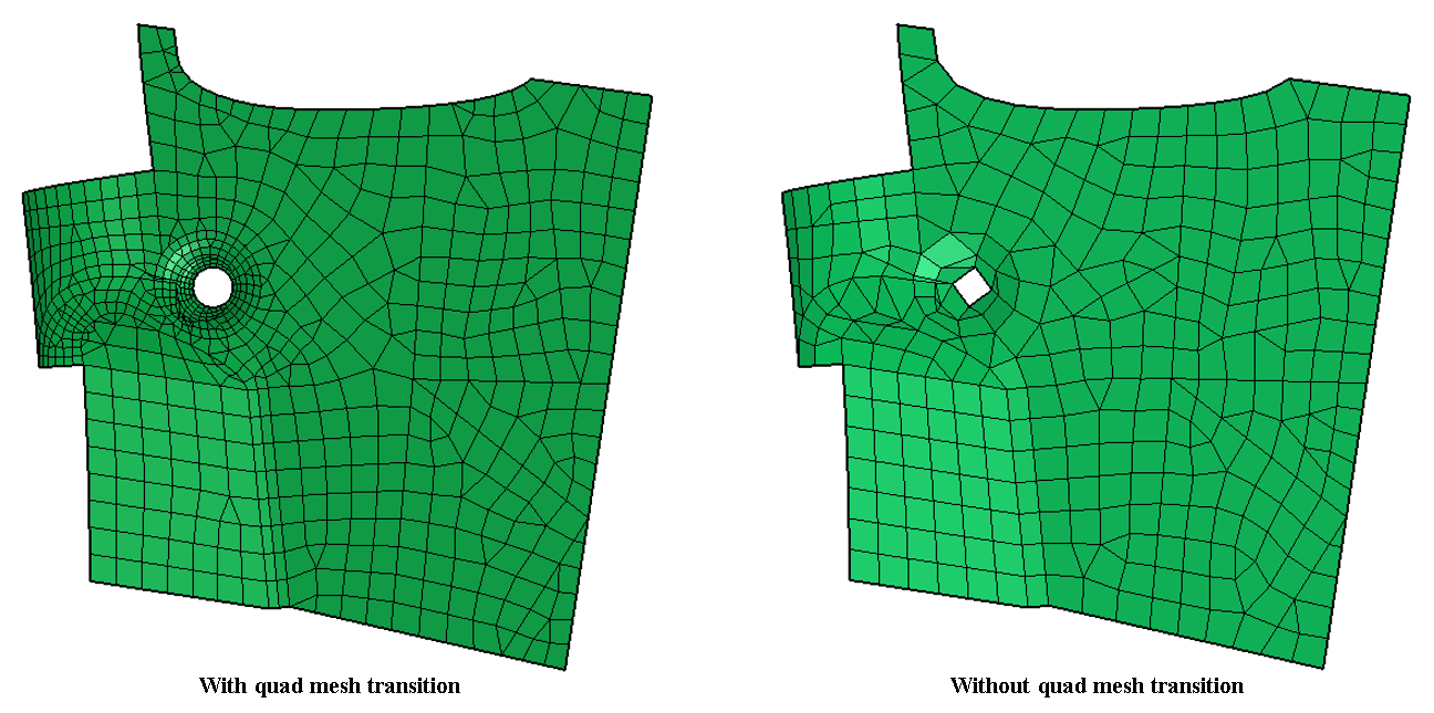
- Allow Quad Mesh Transition
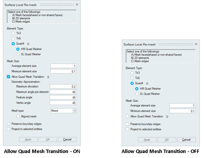
If Allow Quad Mesh Transition is disabled meshing method will be set to “Size and Bias” method of Hyper Mesh. It produces a mesh with consistent element size without any mesh transition.
Enabling Allow Quad Mesh Transition will change meshing method from “Size and Bias” to “Edge deviation” method of Hyper Mesh. In addition to the minimum and maximum mesh sizes, other mesh parameters like maximum deviation, maximum angle per element, feature angle and vertex angle can be used to control the output mesh.
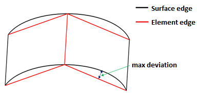
- Maximum deviation
It is the maximium allowable deviation between the element edge and the surface edge. To meet this requirement, element edge lengths along a curved surface edge are reduced as needed to a lower limit set by the min elem size.
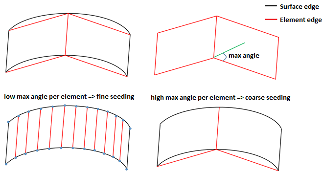
- Maximum angle per element
It defines the maximum allowable angle between two element edges. In case of curved egdes, the curvature will be captured based on maximum angle per element. This also helps to determine the size of an element to create. If the angle formed by adjacent element edges would exceed this value, smaller elements are tried until the angle is equal to or less than this value.
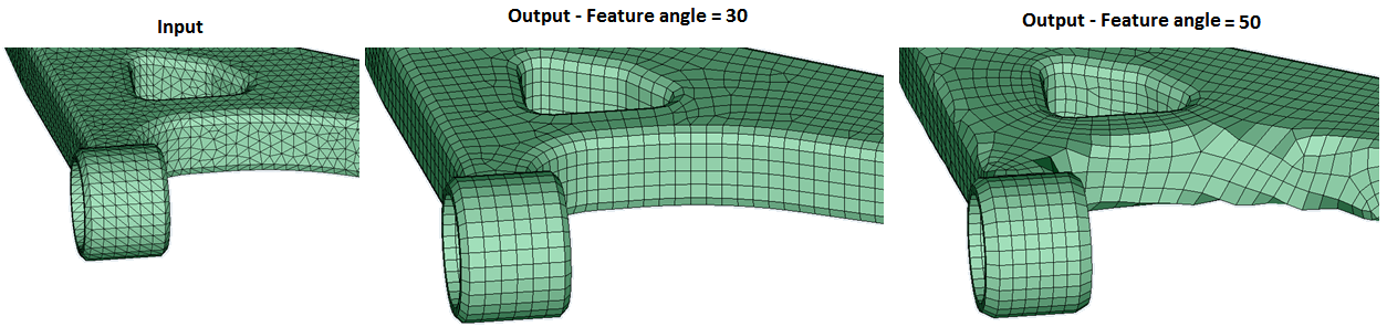
- Feature angle
It is the angle between the two elements normal. This will be used to capture the features efficiently. When the angle between the two element normal are greater than the specified value, additional elements will be introduced based on the given mesh sizes in order to maintain the features. Below example will tell us how the feature angle is used to maintain the feature in output mesh.
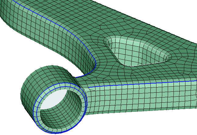
- Vertex angle
It is the angle between three nodes along the feature line. If this angle exceeds than the specified vertex angle, additional nodes will be introduced in between these three nodes. In below image, feature line is highlighted in blue for a feature angle of 30 degree.
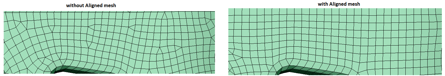
- Aligned mesh
Aligned mesh will be used to get more quad dominated orthogonal mesh. It will work for mixed element type only.
- Project to selected entities
Project to selected entities will be used to project the nodes of the output FEM entity onto the corresponding input entity.
- Mesh Type
- Mixed: Generates Quad mesh with Tris as transition elements.
- Quad dominant: Generates Quad mesh with Quads as transition elements, (wherever possible).
- All quad: Generates an All quad mesh (with no Tris).
- Mesh controls supported
Body mesh control is supported. The mesh output will contain Quad4 elements.
Edge mesh control is supported.
Preserve Entities : Mesh - Edge is supported. The mesh in the preserved edges will be retained in the output mesh.
Note: Value remembrance is not supported for HM quad mesh.