SimLab Molding Interface - Export Settings
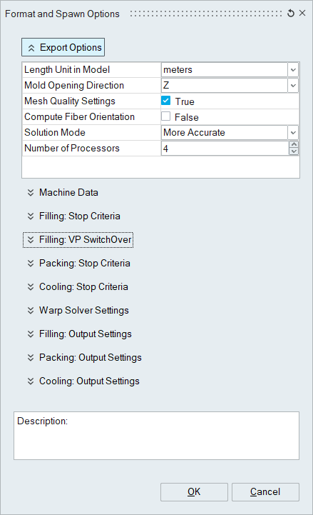
Export Options
- Length Unit in Model: Models must be in one of the following length units:
- Meters
- Millimeters
- Inches
- Mold Opening Direction: The, “mold open direction,” can be along any axis but
not any vector. Currently the mold open direction must be along one of the
global axes.
- X
- Y
- Z
- Mesh Quality Settings
- True/False
- True = If any elements or nodes in the model are of low enough quality to be considered, “Not Supported,” then the analysis will not start.
- Compute Fiber Orientation
- True/False
- True = Turn on fiber orientation calculations in the analysis. These will add time to the simulation, but for fiber filled materials this is required for warp analyses to be accurate.
- Solution Mode
- Fast/More Accurate
- Fast - Solver run in fast mode.
- More Accurate - Solver run in accurate mode.
- Number of Processors
- Text field to specify the number of cores for solver
- Fast/More Accurate
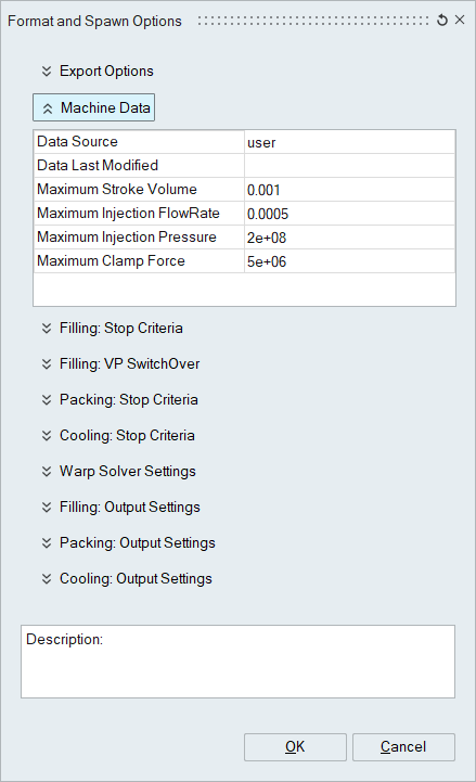
Machine Data
- Data Source:
- Text field to credit the source of the machine data.
- Data Last Modified:
- Text Field to credit the age of the known data.
- Maximum Stroke Volume:
- The volume, in cubic meters, of the extruder when the screw is fully retracted. This does not include the nozzle attached to the barrel, but only the volume represented for the range of travel for the screw.
- Maximum Injection Flow Rate:
- This is the maximum volumetric flow rate in cubic meters per second for the machine. This can usually be found in the machine’s manual, or on a plaque affixed to the machine.
- Maximum Injection Pressure:
- This is the maximum PLASTIC pressure that the machine can produce with the current screw. This can be calculated from the maximum hydraulic pressure multiplied by the screw’s “Intensification Ratio.” Example: (Hydraulic: 2,000psi) * (IR = 3:1) = 6,000psi
- Maximum Clamp Force:
- This is the maximum clamp force for the machine in Newtons. A value of 5,000,000 N is equivalent to 560 Tons (Imperial).
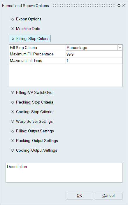
Filling: Stop Criteria
- Fill Stop Criteria
- Percentage:
- Default = 99.9%, can be as low as 99.5% for complete filling of the mold.
- Setting this value to 100% will cause numerical convergence problems.
- The use of lower values (e.g. 20%, 30%, 70%, …) can be thought of as an electronic form of a “short shot study.” This is a type of test performed at the press where the shot size is reduced in order to force a short shot from the machine. This is used to study the filling pattern at the press.
- Time:
- This is not done at the press, but for analysis purposes, if the flow front is taking slowing down because the transfer is too far back, or the flow length designed into the model is too long, then by limiting the fill time, one can cut off the polymer flow if the flow front advancement might produce a short-shot, thus saving on compute time to come to the same conclusion. If the user determines the value of the volumetric flow rate from a desired fill time, then an extra 10-20% should be all that’s needed to save on otherwise-wasted CPU cycles.
- Both: If either criteria is met, the filling analysis is stopped.
- Percentage:
- Maximum Fill Percentage: Designated value
- Maximum Fill Time: Designated time in seconds.
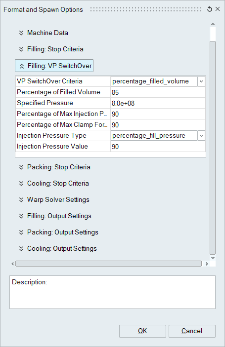
Filling: VP Switchover
- V/P Switchover Criteria
- All_switchover_criteria:
- If ANY of the criteria are met, switchover will happen.
- Percentage_filled_volume:
- Switchover occurs at the designated percent volume filled for the model. Testing at the press indicates that this is typically between 70 and 90 percent filled. This value tends to be affected by the ratio of the runner system’s volume compared to that of the molded parts.
- Specified_pressure:
- When a designated injection pressure is achieved at the inlet face, the process will transfer from velocity control to pressure control.
- Percentage_max_injection_pressure:
- When the plastic injection pressure reaches a designated percent of the machine’s limit, then the process will transfer to pressure control.
- Percentage_max_clamp_force:
- Transfer to pressure control will occur when the designated percent of the machine’s maximum clamp force is achieved. While this is not something that is typically done at the press, if the required clamp force to keep the mold shut limits the ability to run the part, then the analyst will see the transfer happen earlier than anticipated and can begin to diagnose from there. Flow imbalance may be the culprit and could then be focused upon to prevent a spike in pressure and the resulting load on the machine’s tie-bars. This results in less material quietly given away with each part as exceeding the machine’s clamp force will open the mold and deposit extra material that is not accounted for in production planning.
- None:
- No switchover to pressure control. The entire filling process is controlled by flow rate.
- All_switchover_criteria:
- Percentage of Filled Volume: Specified Value
- Specified Pressure: Specified pressure in Pascals
- Percentage of Max Injection Pressure: Specified Value
- Percentage of Max Clamp Force: Specified Value
- Injection Pressure Type
- Pressure_value
- Percent_fill_pressure
- Percent_max_machine_pressure:
- Injection Pressure Value: The value in this field is relative to the IP-Type selection immediately preceding it.
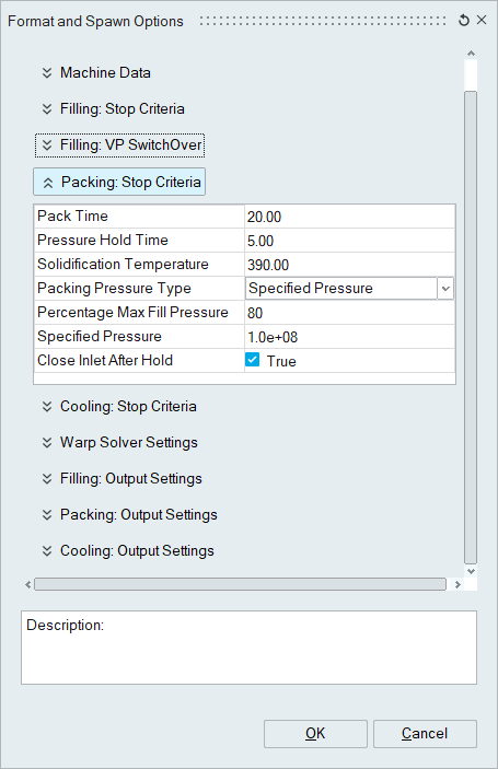
Packing: Stop Criteria
- Pack Time
- Designated maximum pack/hold time after which the packing simulation will be stopped, regardless of whether the gate is frozen. If the gate freezes before this time is achieved, the pack analysis will finish because the objective of this part of the molding process is to keep the density of the part constant until the gate freezes and material can no longer flow back into the runner.
- Pressure Hold Time: Maximum Hold Time for packing analysis.
- Solidification Temperature
- Designated temperature in Kelvin
- Packing Pressure Type
- Percentage Max Fill Pressure
- Specified Pressure
- Percentage Max Fill Pressure: Designated value (Default: 80%)
- Specified Pressure: Designated pressure in Pascals (Default: 1.0e+08 Pa = 100MPa)
- Close Inlet After Hold: With the runner not being critical to the process, this
fixes the mass of the material in the runner system after the gate freezes. This
speeds up the simulation.
- True/False (Default: True)
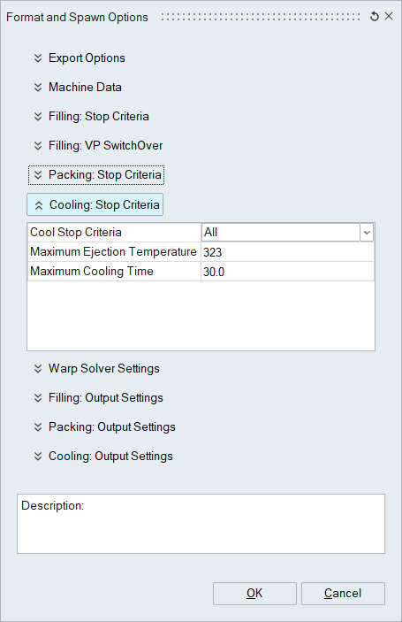
Cooling: Stop Criteria
- Cool Stop Criteria
- Ejection Temperature
- Cooling Time
- All
- If either criteria is met, the cooling analysis will be terminated. For the analyst, if the part cools enough to eject or the maximum target cooling time is reached the analysis is terminated. The time parameter can be used to limit the maximum cycle time and indicate that more development is needed to cool the part quicker so that the process will fit within a profitable window.
- Ejection Temperature
- Maximum Ejection Temperature
- Specified temperature in Kelvin such that if all elements in the mold cool to this temperature or lower then the mold is ready to be opened.
- Maximum Cooling Time
- Specified maximum cooling time in seconds such that if this time is achieved then the cooling analysis is terminated, and a final state is exported.
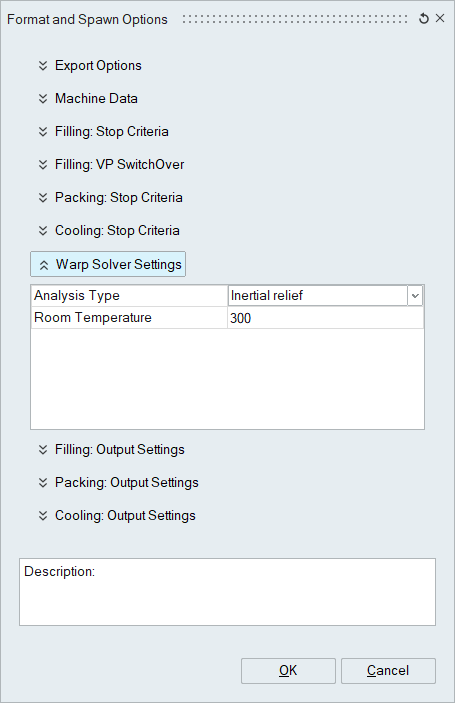
Warp Solver Settings
- Analysis Type
- Inertia Relief
- Inertial relief is a numerical method used to fix the center of mass and the net mass moments of inertia for a part while still allowing the part to naturally deform.
- By Constraints
- If the results of a warp analysis are to be compared to the measurements of a Coordinate Measuring Machine (CMM) then the use of constraints to mimic those of the quality fixture may be helpful to making this comparison.
- Inertia Relief
- Room Temperature
- Designated temperature in Kelvin for the ambient temperature. For instance, 21 degrees Celsius = 294.15 Kelvin.
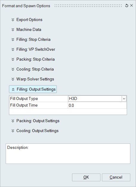
 Output Settings for Filling, Packing and Cooling (Each one has the same
options)
Output Settings for Filling, Packing and Cooling (Each one has the same
options)- Fill Output Type
- H3D
- None
- Fill Output Time: 0.0 (Default)
- Output will be at the nearest cycle after the set time has passed. For example, setting this to 0.5 will output roughly every 0.5 seconds, but because the time steps are variable, there is no guarantee that there will be a time step exactly at each 0.1 seconds, so the next available time step will then output.
- Setting this to 0.0 will export every iteration’s output.