Overview of Model Setup
Introduction
This page gives a quick overview of the steps required to setup the models.- General Guidelines for Model Setup and Simulation
- Setting Up a Model with Only Polymer Parts
- Setting Up a Model with Polymer Part and Part Insert
- Setting Up a Model with Polymer Part, Mold and Part Inserts
General Guidelines for Model Setup and Simulation
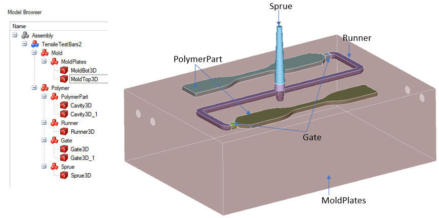
- Part assembly should be correctly organized in Model Browser
- Polymer
- PolymerPart
- Sprue
- Runne
- Gate
- Mold
- MoldPlates
- MoldInsert
- PartInsert
In Molding application, user can select the body and classify bodies using below right click menu.
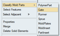
- Polymer
- The term PolymerPart, indicates the part cavity. There is a subtle difference between the part cavity and the molded part. Often the part cavity is sized up by few percentage to compensate for shrinking.
- For a model with multiple gates, different Injection_BC must be applied for every inlet. They should not be clubbed together.
- Before the deck can be exported, all BCs under loads and constraints should be applied correctly.
- Material and properties: Polymer material should be assigned for polymer bodies.
- Solver uses SI units (m) for solving. Define scaling factor in Export | Advanced Options | Export Options | "Length Unit in Model".
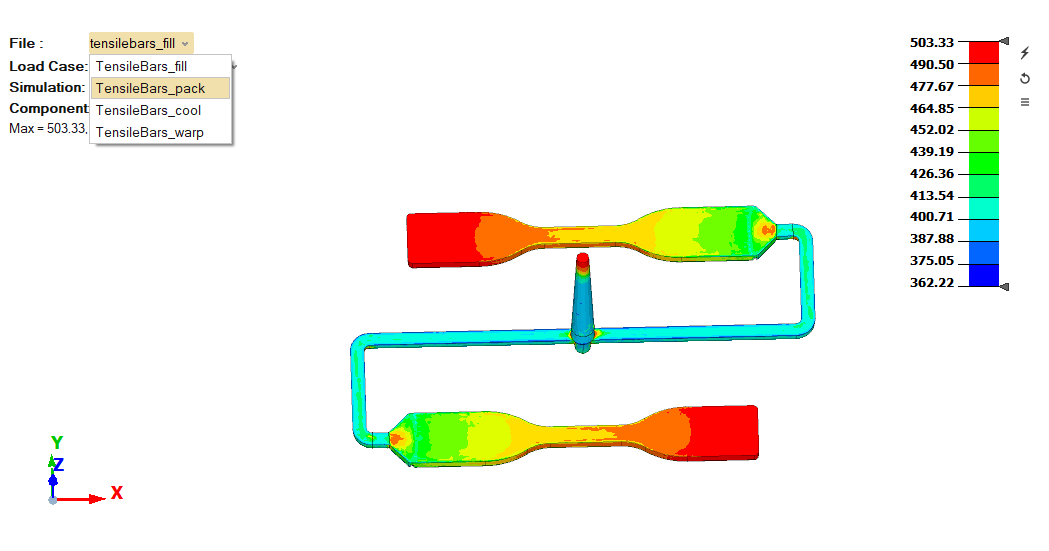
- Results: Multiple results file import supported for molding analysis. Based on
the type of analysis, it will load the multiple files automatically when we attach
results file.
Setting Up a Model with Only Polymer Parts
In this model, we have only the polymer parts. It does not have mold plates, mold
inserts and part inserts. This procedure is applicable for:
- Single or multi-cavity molds.
- Polymer part with gate.
- Models with entire runner system.
- Create a finite element mesh. See the page on meshing guidelines for more details.
- Organize the solid element mesh into gate, sprue, runner and polymer part. This
is done by
- Selecting the corresponding body.
- Right click on the graphics area and click on “Classify Mold Part” option.
- Load a material from material database.
- You can also create a material on the fly and use it.
- Assign this material using properties to the parts.
- Create a solution in the solution browser.
- Set a working folder.
- Pick the type of analysis to be performed (i.e Filling, Packing, Cooling and/or Warping).
- Create initial conditions.
- This essentially assigns the initial temperature for analysis. This is same as the injection temperature for the polymer melt.
- Create the boundary conditions
- Create injection BC on the inlet surface where the polymer injected.
- Create vent BC. If you don’t specify vents, automatic venting option will be used.
- Create convection heat transfer BC on all other polymer surfaces that come into contact with mold.
- Create Export Settings in the solution browser.
- Renumber the model.
- Save the model.
- Either export the deck or launch the run.
Setting Up a Model with Polymer Part and Part Insert
In this model, we have polymer parts along with part inserts. However, it does not have
mold plates, mold inserts and part inserts. This procedure is applicable for:
- Single or multi-cavity molds
- Polymer part with gates
- Models with entire runner system
- Create a finite element mesh. See the page on meshing guidelines for more details.
- Insert mesh should be disconnected from the polymer mesh.
- It is best to mesh them as connected mesh with shared surfaces and then finally separate them.
- Organize the solid element mesh into gate, sprue, runner and polymer part. This
is done by
- Selecting the corresponding body.
- Right click on the graphics area and click on “Classify Mold Part” option.
- Load a material from material database.
- You can also create a material on the fly and use it.
- You have to load materials for both the polymer and the insert.
- Assign this material using properties to the parts.
- Creating a solution in the solution browser.
- Set a working folder.
- Pick the type of analysis to be performed (i.e Filling, Packing, Cooling and/or Warping).
- Create initial conditions.
- This essentially assigns the initial temperature for analysis. This is same as the injection temperature for the polymer melt.
- Initial condition for the part insert specifies the initial insert temperature.
- Create boundary conditions.
- Create injection BC on the inlet surface where the polymer injected.
- Create vent BC. If you don’t specify vents, automatic venting option will be used.
- Create convection heat transfer BC on all other polymer surfaces that come into contact with mold.
- Create contact conditions between the polymer parts and the insert.
- Create heat transfer condition on the surfaces of the insert that come in contact with the mold. This is also done using the “Convection” icon. For this, use the heat transfer coefficient type as “Mold Ambient” and specify the average mold temperature as the temperature and 1000.0 W/m^2-K as the contact heat transfer coefficient.
- Create Export Settings in the solution browser.
- Renumber the model.
- Save the model.
- Either export the deck or launch the run.
Setting Up a Model with Polymer Part, Mold and Part Inserts
In this model, we have
- Polymer parts
- Part inserts (optional)
- Mold plates
- Mold inserts (optional)
- This procedure is applicable for:
- Single or multi-cavity molds
- Models with entire runner system
- Create a finite element mesh. See the page on meshing guidelines for more details.
- Mesh for the mold plates and inserts. This should be disconnected from the polymer mesh.
- It is best to mesh them as connected mesh with shared surfaces and then finally separate them.
- Now the mesh is connected between mold and inserts.
- Organize the solid element mesh into gate, sprue, runner and polymer part. This
is done by
- Selecting the corresponding body.
- Right click on the graphics area and click on “Classify Mold Part” option.
- Load a material from material database.
- You can also create a material on the fly and use it.
- You have to load materials for both the polymer, mold plates and the insert.
- Assign these materials using properties to the corresponding parts.
- Create a solution in the solution browser.
- Set a working folder.
- Pick the type of analysis to be performed (i.e Filling, Packing, Cooling and/or Warping).
- Create initial conditions.
- This essentially assigns the initial temperature for analysis. This is same as the injection temperature for the polymer melt.
- Initial condition for the part insert specifies the initial insert temperature.
- Create boundary conditions.
- Create injection BC on the inlet surface where the polymer injected.
- Create vent BC. If you don’t specify vents, automatic venting option will be used.
- Create convection heat transfer BC on all external surfaces of the mold.
- Create contact conditions between the polymer parts and (mold+Inserts).
- Create Export Settings in the solution browser.
- Renumber the model.
- Save the model.
- Either export the deck or launch the run.