Motion

Introduction
The Motion allows you to define the motion of some bodies or/and non-meshed coils of the solution. It allows to make several simulations corresponding to different moving bodies positions by launching only one solving.
Dialog Box
| Translation type motion | Rotation type motion |
|---|---|
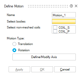 |
- Select bodies / coils which are moving. At least, one body must be selected.
- Motion Type: Two choices are proposed:
- Translation
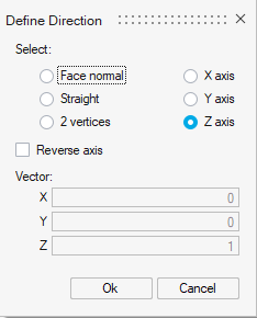
Translation direction has to be chosen through Define/Modify Direction button:
- Rotation
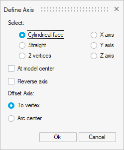
Rotation axis has to be chosen through Define/Modify Axis button:
- Translation
Motion parameters
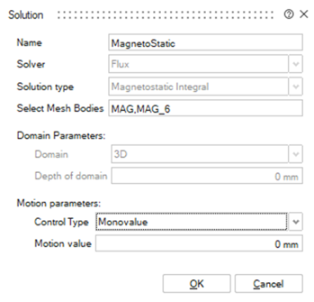
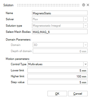
Once the motion entity is created, the Solution box content is updated with Motion parameters inputs to pilot the motion during the solving:
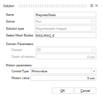
| Solution with Monovalue Motion parameters | Solution with Multivalues Motion parameters |
|---|---|
 |
 |
Monovalue Motion parameters allow to solve for one position defined by an offset distance or angle (respectively for translation and rotation) applied on the initial position.
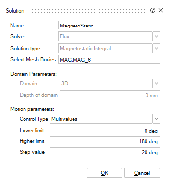
Multivalues Motion parameters allow to solve for several positions defined by a Lower limit, a Higher limit and a Step value. Those values correspond to distance or angle offsets (respectively for translation and rotation) applied on the initial position.
Steps for Translation
In this section, we will show the steps for translation case on an example of linear actuator:
-
Click on the Motion button:
→ A default direction of the translation with an arrow on Z is visible at Motion box opening. This will be changed in following steps.
- Select bodies which are moving.
In this case, the body highlighted in red in the upper image.
→ The selected bodies are highlighted, and the corresponding field in the dialog box is filled with selected bodies names.
- Select Motion type as Translation
- Open Define/Modify Direction.
Select Y axis and OK.
→ The preview of the translation direction is correctly updated.
-
Click on Ok.
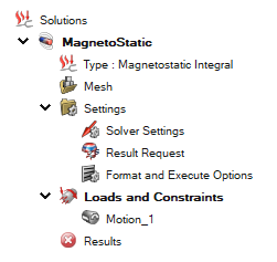
→ The Motion is created and appears in the Solution Browser (2nd tab) in the node Loads and Constraints
-
Once the motion entity is created, the motion has to be piloted for the solving. This has to be done in the Solution box which contains now Motion parameters inputs.
-
Click on the Edit solution button:

→ The solution box contains now Motion parameters inputs with by default Monovalue control type set to 0.
-
We will choose for this example Multivalues motion parameters to solve at different positions.
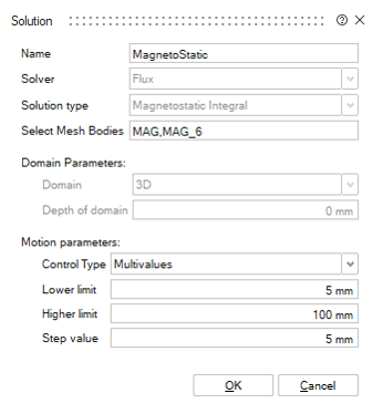
- Select Control type: Multivalues
- Enter Lower limit distance value
- Enter Higher limit distance value
- Enter Step value distance value
- Click on OK
→ The project is ready to be solved.
-
Steps for Rotation
In this section, we will show the steps for rotation case on an example of a rear-view motor:
-
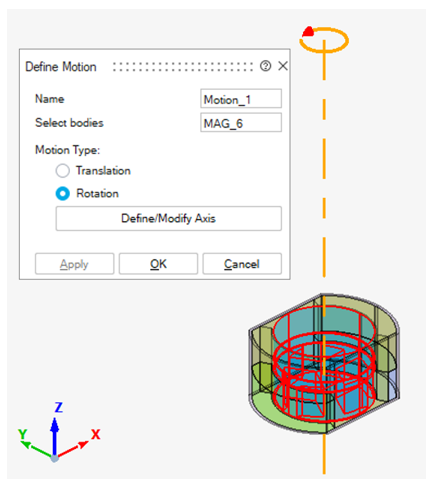
Click on the Motion button:
- Select bodies which are moving.
→ The selected bodies are highlighted, and the corresponding field in the dialog box is filled with selected bodies names.
- Select Motion type as
Rotation
→ The preview of the default rotation axis is displayed (Z axis) which is the right one on this example.
- If needed, it is possible to open Define/Modify Axis to select another rotation axis.
-
Click on Ok.
→ The Motion is created and appears in the Solution Browser (2nd tab) in the node Loads and Constraints
-
Once the motion entity is created, the motion has to be piloted for the solving. This has to be done in the Solution box which contains now Motion parameters inputs.
Please follow Step 6 of Steps for Translation and enter the angular offset positions (in degree) to be simulated.
→ The project is ready to be solved.