Thin Region

Introduction
The Thin Region Load and Constraint enables modeling bodies with a small thickness.
It simplifies the model set-up, especially the meshing.
The meshing and solving processes are executed more efficiently and rapidly.
Thin Region types and inputs
Here is an example of Thin Region dialog box of Air gap type:
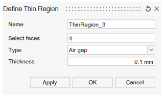
First of all, Thin Region name is entered, and faces defining the Thin Region are selected.
- In 3D Magnetostatic solution, the following 2
Thin Region types are available:
- Air gap:
- Enter a thickness value
- Magnetic non-conducting:
- Enter a thickness value
- Assign a material with soft magnetic property
- Define the boundary condition with magnetic field direction (tangent / normal / no restriction)
- Air gap:
Constraints
Here are some constraints on the Thin Region usage:
-
Thin Region faces of the following types cannot be on the periodicity or symmetry plane:
- Air gap
- Magnetic non-conducting with Boundary condition defined by Almost normal magnetic flux or No restriction in the magnetic flux direction
- If there is a Motion, Thin Region faces and its edges cannot be at the interface of bodies having different Motion information.
Post processing on the Thin Region
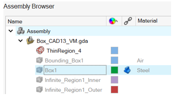
At the end of solving, a shell body associated to each Thin Region is automatically created to allow the post processing on it. The Shell body name corresponds to the Thin Region name.
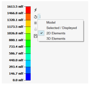
In order to see Contour/Vectors on the Thin Region shell body:
-
Display the shell body and hide the solid bodies in contact with it
- Select the following option: 2D
Elements
The available quantities are:
- The magnetic flux density B for all Thin Region types.
Limitations
Here are some current limitations on the Thin Region:
- If a shell body associated to a Thin Region already
exists in preprocessing, the Infinite box creation does not work.Note: Shell body usually exists in preprocessing when its CAD faces are not belonging to a solid body: faces are immerged inside a solid body.The workaround is to:
- Create a bounding box containing the shell body.
- Tet mesh the bounding box with all the bodies inside. Then, the shell body disappears from the model, but the bounding box solid mesh keeps the shell body surface mesh.
- Hide a face from the bounding box to be able to select the shell body face in the Thin Region Load and Constraint.
-
Concerning the Thin Region of type:
- Air gap
- Magnetic non conducting with Boundary condition defined by Almost normal magnetic flux or No restriction in the magnetic flux direction
there is a potential gap. Therefore the results are different on the considered side. A current limitation is that only one of two sides is displayed.