Sheet Lamination

Introduction
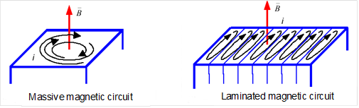
The Sheet Lamination allows to define stacked magnetic sheets and allows to compute iron losses in Transient and AC analysis (only Bertotti model at this time).
This Load enables the modeling of a laminated part: magnetic (permeability μr) non conducting, like stacked magnetic sheets simplified via the homogenization method.
With Sheet lamination load, there is not need to represent geometrically each sheet.
- a stacking factor:
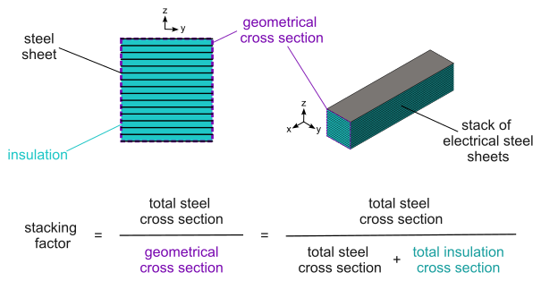
The sheet lamination is said to be laminated because it automatically accounts for the effect of the insulation of the electrical steel and for the small air gaps between the sheets in a stack. This is achieved through a homogenization procedure implemented. The overall effect of this homogenization is that the effective cross-section of magnetic material available for the magnetic flux to traverse in the region is reduced. The reduction factor is known as the stacking factor of the region, and corresponds to the total cross section area occupied by magnetic material (steel) in the stack divided by the surface area of the geometrical cross section of the same stack (i.e., the total cross section area, including the insulation and air gaps between sheets). This definition is illustrated below:
Sheet Lamination Dialog Box for 3D Transient Magnetic, 3D AC Magnetic, and 3D Magnetostatic solutions
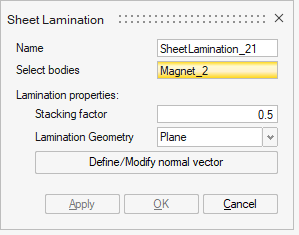
- Select bodies: one or several bodies to define as sheet lamination.
- Lamination properties:
- Stacking factor
- Lamination Geometry2 types:
- Plane
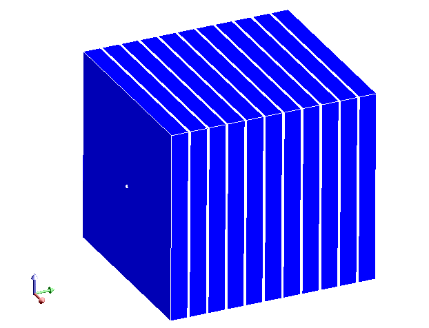
The direction of the planar sheet lamination is defined by a normal vector, by clicking on Define/Modify normal vector
- Cylinder
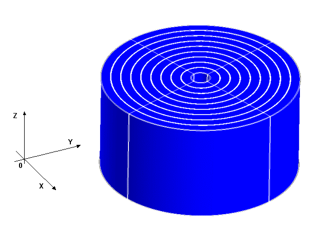
The direction of the cylindrical sheet lamination is defined by the cylinder axis, by clicking on Define/Modify cylinder axis
- Plane
Steps
- Check the prerequisites:
-
a Soft Magnetic Material should be assigned to the body. To compute the iron losses in transient and AC analysis, the Bertotti parameters should be defined.
-
- Click on the Sheet Lamination
button in Analysis ribbon:

- Select bodies: Select one or several bodies to define as a sheet lamination.
- Choose the Stacking factor
- In 3D, define the Lamination Geometry
- Validate by clicking on OK
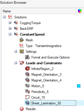
→ The sheet lamination is created and appears in the Solution Browser in the Loads and Constraints node.