Surface Mesh
![]()
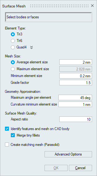
Introduction
Global parameters to mesh surfaces of a body with 2D elements (TRI/QUAD) is specified using the Surface Mesh dialog box. The 2D element types supported are:
- Tri3
- Tri6
- Quad4
Tri Mesh Parameters
The parameters to create Tri3 and Tri6 mesh are explained below
Element Type
This option can be used to create a Tri3 or Tri6 surface mesh.
Mesh Size
- Average element size
The Average Element Size is the average element edge length for Tri/Quad elements. The element edge length will vary between (Average Element Size)*Sqrt(2) and (Average Element Size)/Sqrt(2).
- Maximum element size
This toggle allows the user to choose Maximum Element Size instead of Average Element Size. When Maximum Element Size is specified, then the mesh will have no elements with edge length greater than this value.
- Minimum element size
The Min Element Size is used to remove all the elements that have element edges less than this value.
- Grade factor
The mesh size transition on a surface mesh is controlled by Grade Factor. Default Grade Factor value is 1.5. (Average Element Size marches 1.5 times from fine to coarse).
Geometry Approximation
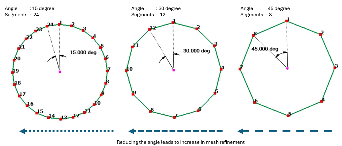
In case of curved surfaces, the curvature is captured based on Maximum angle per element and Curvature minimum element size along the curvature direction. By varying the Maximum angle per element and Curvature minimum element size, the desired geometry approximation can be attained.
The default Maximum angle per element is 45 degrees. This will create 8 elements on a circular hole. A better approximation of the surface can be obtained by using a smaller Maximum angle per element. If the Maximum angle per element is reduced to 30 degrees, 12 elements will be created on a circular hole. For a very small hole the Maximum angle per element will create tiny elements and might not be desired. The creation of tiny elements can be prevented by setting the Curvature minimum element size. The geometry will be approximated using the angle as long as the resulting element edges are greater than the Curvature minimum element size. Otherwise, the Curvature minimum element size will be used to define the mesh size.
Aspect ratio
The quality of mesh can be controlled by setting the Aspect Ratio. The value can vary from 1 (equilateral element) to infinity (straight line). The default Aspect Ratio is set to 10.
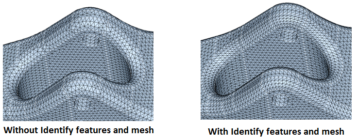
Identify features and mesh on CAD body
Identify features and mesh on CAD body will mesh the fillets and cylinders as if the fillet and cylinder mesh controls are applied with the global meshing parameters. Mesh size, curvature angle, curvature minimum size and aspect ratio will be derived from the global meshing parameters applied either through body mesh control or in the mesh generation form. Fillets with radius less than “Global mesh size * 15” only will be considered and rest of the fillets will be ignored.
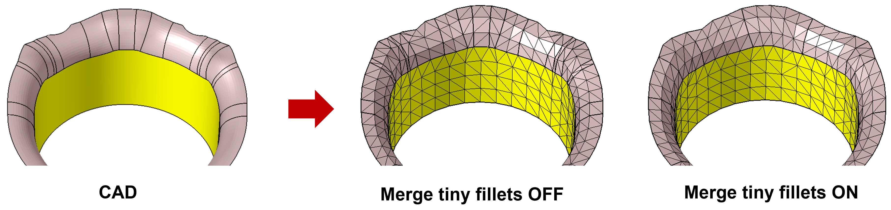
Merge tiny fillets
When this option is turned ON, fillets having only one element along its length (i.e., length along the fillet) are considered as tiny fillets and will be merged with the adjacent fillet.
It will work with “Identify features and mesh” option and supported only for CAD.
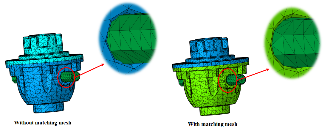
Create matching mesh (Parasolid)
This option will create matching mesh between Parasolid bodies that are in contact.
Matching mesh will be created by connecting Parasolid bodies using Boolean -> Combine operation.
Limitations
- Supported only for Parasolid geometry.
- Input CAD will be modified to make a connected body.
- Mesh output will always be created in a new model.
- The below mesh controls will be deleted or modified on bodies that get
connected in Boolean operation.
-
Fillet/cylinder/proximity/washer/remove hole mesh controls assigned to bodies (not faces) will be deleted.
- Body-based mesh controls like body, volume layer and region mesh controls on the original bodies will be transferred to new connected CAD bodies as face-based.
- Edge bias seeding, include, symmetry (if not valid after Boolean) and hard points will be deleted.
-
- Face (both CAD and FEM) input: Mesh output will be created in a new model.
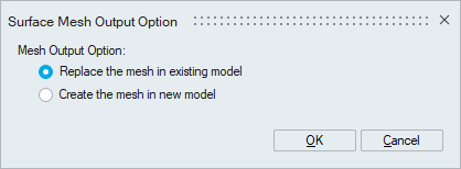
- FE body input: Below message will be posted and the user
needs to choose whether to replace the existing mesh or to create
the output in a new model.
- CAD body
- If a CAD model has meshed for the first time, mesh output will be created in a new model.
- The subsequent meshing of CAD model
- If input CAD bodies do not have equivalent mesh in
the existing FE model, the mesh output will be
created in the existing FE model.
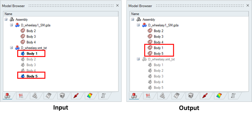
- If input CAD bodies have equivalent mesh in the
existing FE model.
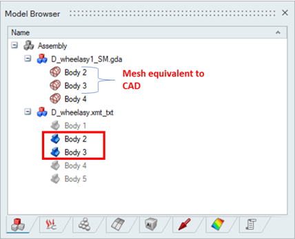
The following message will be posted. Based on user's selection, mesh output will be created in a new model or in the existing model.
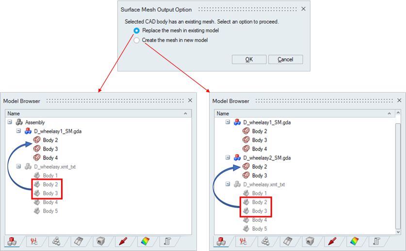
- If input CAD bodies do not have equivalent mesh in
the existing FE model, the mesh output will be
created in the existing FE model.
- Replace bodies in the existing model is not supported for bodies assigned with Region mesh control - body break option.
- Whenever the CAD bodies are meshed and the mesh output is replaced on the existing FE bodies which are shared. The shared faces will not be retained in the output.
- If the input FE body has solid elements, the output cannot be replaced in the existing model.
- If the input FE body has angular symmetry or edge bias seeding mesh controls, replacing the output in the existing model will delete the above-said mesh controls.
Multi core meshing
- Mesher uses single core as default, to perform the meshing. When an assembly has multiple bodies, single core meshing will mesh one body at a time. So the total time taken is the sum of the time to mesh each body. If the hardware supports multiple cores, user can request the mesher to use the multiple cores when meshing. When multiple solids are selected to mesh, the mesher will distribute the bodies between the cores and mesh them simultaneously. This will reduce the meshing time for assemblies with large number of bodies. Note that the amount of physical memory in the machine will also determine the performance of meshing. User can specify the number of cores in File | Preferences | Applications | Options. Currently multi core meshing is supported for Parasolid, STEP, CATIA (imported only through File | Import | CATIA - Direct) and SOLIDWORKS.
Instance Meshing
- If instances are present in CAD model, only one of the instances will be meshed and the mesh output will be copied to other instance locations. Currently this is supported only if the instance bodies do not have any mesh controls associated with it.
Tri Mesh Advanced Options
The less often used controls are available in Advanced Surface Mesh Options. These options can be viewed and set once the input entities are selected.
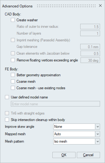
CAD Body
The options which are under "CAD Body" available only for CAD bodies.
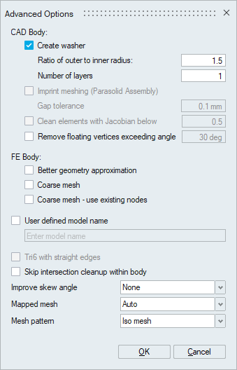
- Create washerCreate washer will create washer around circular edges on planar surfaces.
- Ratio of outer to inner radius
The washer width is calculated based on the ratio of washer outer to inner radius.
- Number of layers
This option specifies the number of layers of element along the width of washer.
- Ratio of outer to inner radius
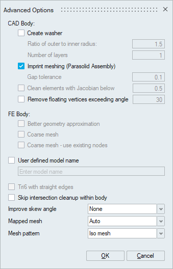
- Imprint meshing (Parasolid Assembly)
Imprint meshing option will be available only when meshing of Parasolid solid bodies which are imported with "Imprint solid bodies" option. This option allows the user to create matching faces between bodies.
- Stitch sheet bodies
Stitch sheet bodies option will be available only when Parasolid or Step sheet bodies are selected for meshing. This option will stitch the selected sheet bodies and ensure the connectivity between them. Gap tolerance will be used to define the gap between the sheets to be stitched.
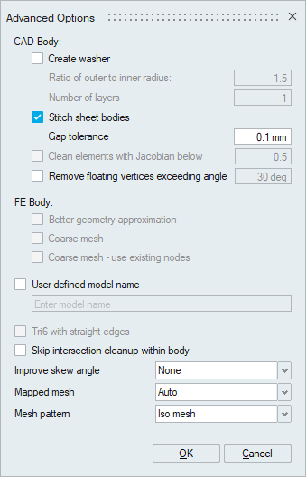
- Clean elements with Jacobian below (Value)
This option helps to clean the TRI6 elements that fail to meet the specified Jacobian quality threshold during the surface mesh.
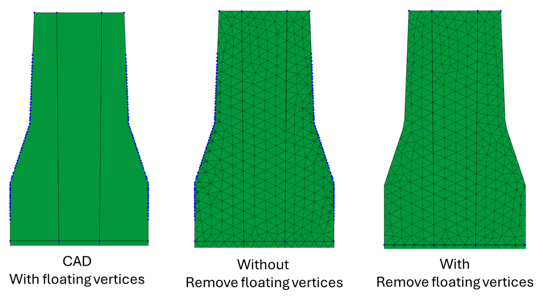
- Remove floating vertices exceeding angle (Value)
In some cases, manifold vertices in the CAD model can affect the quality of the output mesh. This option eliminates manifold vertices in the output mesh that form angles greater than the specified value, ensuring a good-quality mesh output.
FE Body
The options which are under "FE Body" available only for meshed bodies.
- Better geometry approximation
Better geometry approximation option is available only when meshing surfaces of FE bodies. When we import solver input files, a FE body is created. This body has one or more faces based on a feature angle used to break the face. These faces are piecewise planar faces and is a coarse representation of a smooth geometry. Meshing this coarse geometry will result in a mesh that is coarser than the FE body. Turning ON this option will reduce the loss of geometry.
- Coarse mesh
The mesh can be customized based on type of analysis, for example Durability, NVH, etc. For NVH analysis, the features are not given any importance. The aim in NVH meshing is to create a coarse mesh on the geometry. When this toggle is turned ON, a coarse mesh is created.
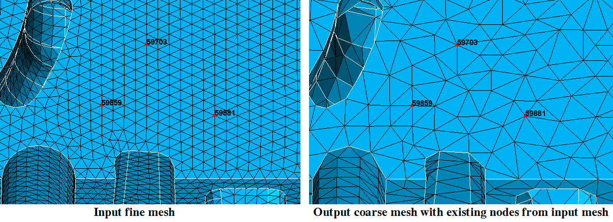
- Coarse mesh - use existing nodes
This toggle allows the user to create a coarse mesh from a fine mesh by using the existing nodes from the fine mesh. The node Ids are retained in the output mesh.
User defined model name
This option will create the output mesh in a new model or rename the existing model with user given name.
Tri6 with straight edges
Tri6 with straight edges option is available only when Tri6 Element Type is chosen. When this toggle is turned ON, the mid nodes of the Tri6 elements will be linearly interpolated between the corner nodes.
Skip intersection clean-up within body
While generating surface mesh, element intersections clean-up will be done for the below cases
- Meshing of CAD – Solid and Connected body
- Meshing of CAD – Sheet bodies with Stitch sheet bodies option
- Meshing of FE Body + Improve skew angle option
Improve skew angle
Improve skew angle option allows the user to improve the skew based on the skew parameter values set in File > Preferences. This is supported for both CAD and FEM inputs. Refer the following link for setting the skew parameter values. Improve skew angle
- None: Improve skew angle option will not be considered while meshing if None is selected.
- Auto: Auto signifies the skew angle improvement by mid-line collapse, zigzag mesh and node movement for tessellation based meshing and only node movement for the CAD meshing.
- Simplify Ribs: Simplify Rib option works only for CAD inputs. Here, the skew angle will be improved by mid-line collapse, projection, reducing the local size and node movement
Mapped mesh
- Auto: The mesher will automatically determine the faces that can be iso-meshed. All regular 4-edged faces and faces that are 4-sided will be iso-meshed.
- Regular 4-sided faces: All regular 4-edged faces, even if the edges are not of similar size will be iso-meshed. Though a mapped mesh is created, the quality can be poor. There is no transition when a surface tapers or enlarges.
- None: Free mesh (the interior angles are closer to 60-60-60 degrees and not 90-45-45) will be forced for all faces in the body, even if it is a regular 4 edged face.
Mesh pattern
Mesh pattern defines the pattern on faces that are mapped meshed.
- IsoMesh : IsoMesh option creates elements that are right angled and the edges of adjacent elements are inclined in the same direction.
- Union jack :Union jack option creates elements that are right angled but the edges of adjacent elements are inclined in the opposite direction.
The iso mesh is done by default on the cylinders and 4sided faces on a FE Body.
- By default, the mesher retains the shared bodies/faces even after meshing. To separate the bodies, use Assembly | Connect | Separate
- When FE faces are selected, the mesher by default does not preserve the mesh along the boundary edges. Boundary edges, here, refers to the edges that are common to the faces to be meshed, and the faces that are not selected for meshing. Free Edges will also be meshed because, it does not come under the list of common edges between the faces to be meshed and the faces that are not meshed
- When the CAD model is imported with Imprint solid bodies option is
meshed from a saved database, the mesher will ask to specify the geom
file.
- If surface meshing is done with imprint meshing option, always
specify the original Parasolid file i.e. select the wheelasm.x_t
instead of wheelasm_imprint.xmt_txt.
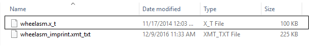
- If surface meshing is done with imprint meshing option, always specify the Parasolid file that is imprinted i.e. select the wheelasm_imprint.xmt_txt.
- If surface meshing is done with imprint meshing option, always
specify the original Parasolid file i.e. select the wheelasm.x_t
instead of wheelasm_imprint.xmt_txt.
- In Imprint meshing,
- region mesh control based on bodies is not supported.
- the attributes will not get transferred from CAD to FE model.
Quad Mesh Parameters
SL quad
The parameters to create a Quad4 mesh can be defined. In Quad mesh, the Min Element Size is set as 1/4th of the Average Element Size. However, this can be modified to suit the requirement.
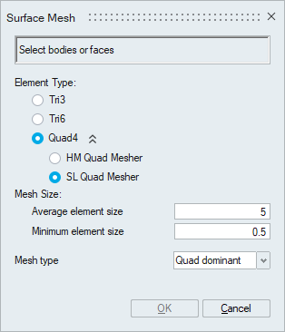
- Mesh Type
- Mixed: Generates Quad mesh with Tris as transition elements.
- Quad dominant: Generates Quad mesh with Quads as transition elements, (wherever possible).
- All quad: Generates an All quad mesh (with no Tris).
HM quad
HM quad works based on the “Size and Bias” or “Edge deviation” method of Hyper Mesh.
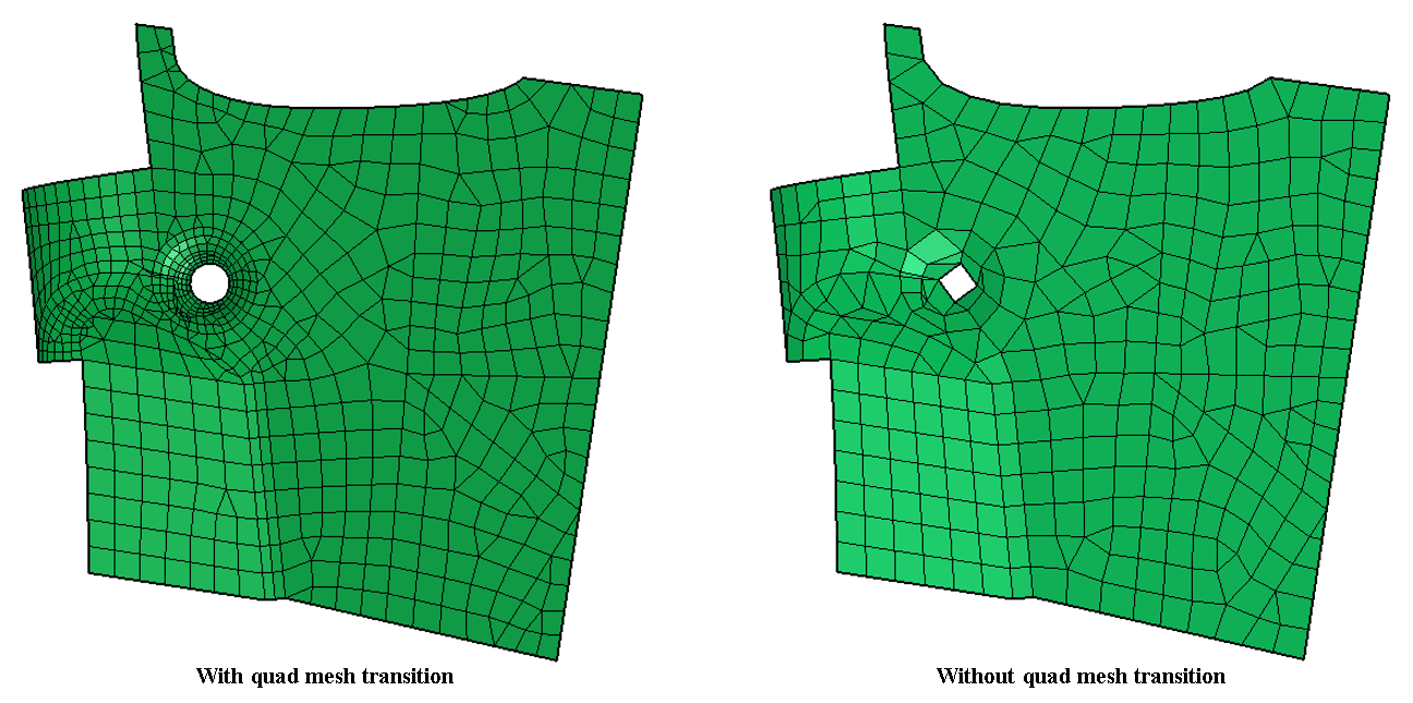
- Allow Quad Mesh Transition
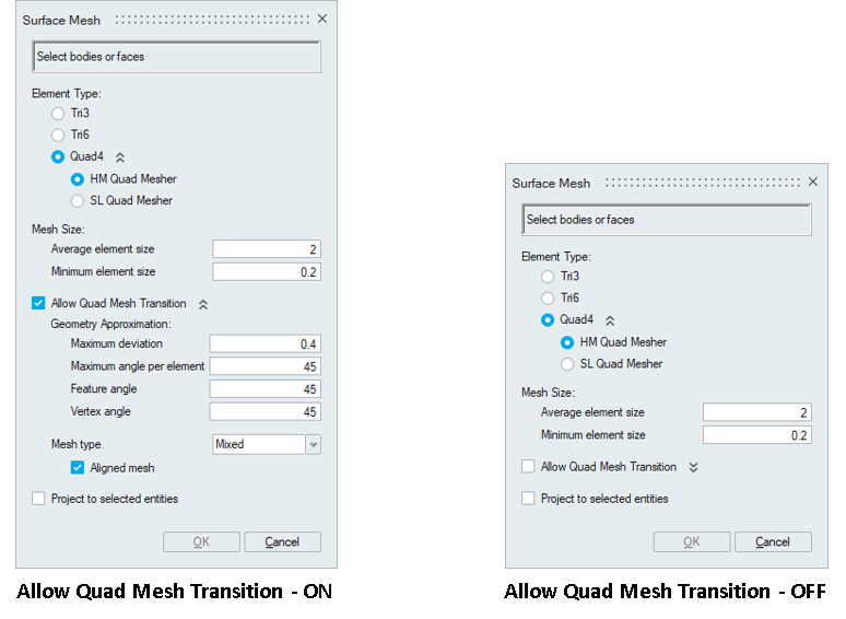
If Allow Quad Mesh Transition is disabled meshing method will be set to “Size and Bias” method of Hyper Mesh. It produces a mesh with consistent element size without any mesh transition.
Enabling Allow Quad Mesh Transition will change meshing method from “Size and Bias” to “Edge deviation” method of Hyper Mesh. In addition to the minimum and maximum mesh sizes, other mesh parameters like maximum deviation, maximum angle per element, feature angle and vertex angle can be used to control the output mesh.
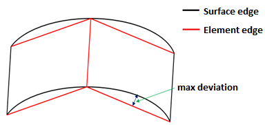
- Maximum deviation
It is the maximum allowable deviation between the element edge and the surface edge. To meet this requirement, element edge lengths along a curved surface edge are reduced as needed to a lower limit set by the min element size.
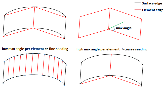
- Maximum angle per element
It defines the maximum allowable angle between two element edges. In case of curved edges, the curvature will be captured based on maximum angle per element. This also helps to determine the size of an element to create. If the angle formed by adjacent element edges would exceed this value, smaller elements are tried until the angle is equal to or less than this value.
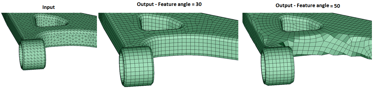
- Feature angle
It is the angle between the two elements normal. This will be used to capture the features efficiently. When the angle between the two element normal are greater than the specified value, additional elements will be introduced based on the given mesh sizes in order to maintain the features. Below example will tell us how the feature angle is used to maintain the feature.
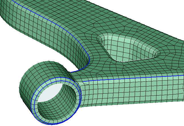
- Vertex angle
It is the angle between three nodes along the feature line. If this angle exceeds than the specified vertex angle, additional nodes will be introduced in between these three nodes. In below image, feature line is highlighted in blue for a feature angle of 30 degree.
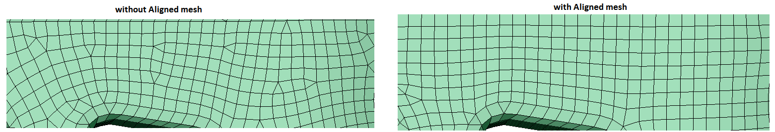
- Aligned mesh
Aligned mesh will be used to get more quad dominated orthogonal mesh. It will work for mixed element type only.
- Project to selected entities
Project to selected entities will be used to project the nodes of the output FEM entity onto the corresponding input entity.
- Mesh Type
- Mixed: Generates Quad mesh with Tris as transition elements.
- Quad dominant: Generates Quad mesh with Quads as transition elements, (wherever possible).
- All quad: Generates an All quad mesh (with no Tris).
-
Mesh controls supported
Body mesh control is supported. The mesh output will contain Quad4 elements.
Edge mesh control is supported.
Preserve Entities : Mesh - Edge is supported. The mesh in the preserved edges will be retained in the output mesh.