Symmetry
![]()
Introduction
Symmetry boundary conditions are used when the physical geometry of interest is symmetric. By applying the symmetry boundary condition, we can reduce the model size, thereby reducing the computation time.
If your device is symmetric, you can define a Symmetry.
The Symmetry allows you to create a symmetry (geometrical and physical aspects).
Symmetry conditions on boundaries
When a device has symmetry planes, it is possible to represent a fraction of the device, and to set appropriate symmetry conditions on the symmetry planes.
From a physical point of view, the symmetry boundary conditions are set on the state variable (potential).
| Tangential Symmetry condition (or symmetry) | Normal Symmetry condition (or anti-symmetry) |
|---|---|
 |

|
Symmetry and infinite box
It is possible to combine infinite box and symmetries. In this case, the geometry of the infinite box (points and lines) automatically follows the symmetries attached to the study domain.
The examples of the infinite box geometry for the study domain with no symmetry and with the symmetries are presented in the table below.
| No Symmetry | Symmetry |
|---|---|

|
 |
| The device is simulated in its full representation. | Two symmetries exist: along X and along Y axis. |
Dialog box
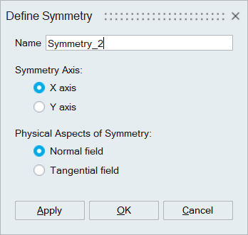
- Symmetry Axis: The device can be symmetric with respects to X and/or Y axis. If the device is symmetric with respects to both axis, two Symmetry entities must be created with each axis.
- Physical Aspects of Symmetry: This option is necessary to define the direction of the electric field near the axis of Symmetry. The electric field can be either Normal field or Tangential field. For more information, please refer to Symmetry conditions on boundaries above.