Create
![]()
This tool is used to create local coordinate system. Rectangular / Cylindrical / Spherical types can be created.
Defining a coordinate system can be done by the following methods:
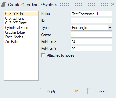
- C, X, Y Point
Select an origin point, point on X-axis and point on Y-axis to define a local coordinate system. SimLab calculates the Z axis orthogonal to X and Y axes.

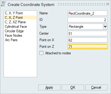
- C, X, Z Point
Select an origin point, point on X-axis and point on Z-axis to define a local coordinate system. SimLab calculates the Y axis orthogonal to X and Z axes.
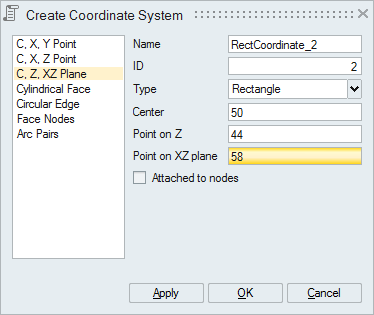
- C, Z, XZ Plane
Select an origin point, point on Z-axis and point on XZ plane to define a local coordinate system. SimLab calculates the Y axis perpendicular to XZ plane and then X axis orthogonal to Y and Z axes.
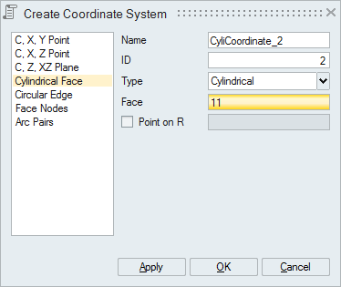
- Cylindrical Face
Select a cylindrical face to define a local coordinate system with Z-axis along the axis of cylindrical face. Also there is an option to define the R-axis by selecting a node.
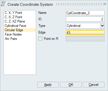
- Circular Edge
Select a circular edge to define a local coordinate system with Z-axis along the axis of circular edge. Also there is an option to define the R-axis by selecting a node.
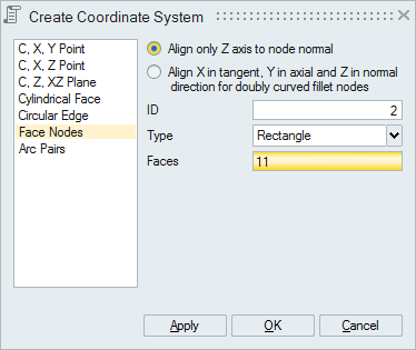
- Face Nodes
Select a face to define local coordinate systems for all nodes of the face.
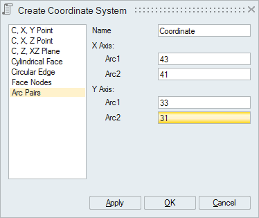
- Arc Pairs
Select two arc pairs to define two local coordinate systems. One of the arc pair will be used to define the X-axis and another arc pair to define the Y-axis.
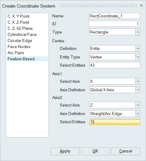
- Feature Based Coordinate
The definition of coordinate centre and axes is based on selected entities. As the selected geometry undergoes any modifications or transformations, the coordinate centre and axes also get updated accordingly.
 The centre can be defined with below options,
- Origin:
The Coordinate centre point is defined at the origin of the global coordinate XYZ (0.0, 0.0, 0.0).
- Entity:
The Coordinate centre is calculated based on the selected entities. User can select the below options,
- Body
- Face
- Edge
- Vertex
- Node
The centre point is at the geometric centre of the selected entities.
User can define any of the two axes. i.e (X and Y) or (Y and Z) or (Z and X). The third axis will be determined automatically by taking the cross product of the first two axis.
The Axis 1 and Axis 2 can be defined by the below options.- Global X Axis
- Global Y Axis
- Global Z Axis
- Face Normal
- Straight/Arc Edge
- Arbitrary
Global X, Y and ZAxis
The local coordinate axis is oriented to the Global X, Y and Z Axis.
Face Normal
The local coordinate axis is parallel to the selected face normal.
Straight/Arc Edge
The local coordinate axis point is calculated based on the selected edge.
If the straight edge is selected, the axis will be along the straight edge.
If the Arc edge is selected, the axis will be parallel with the axis of the arc.
- Origin:
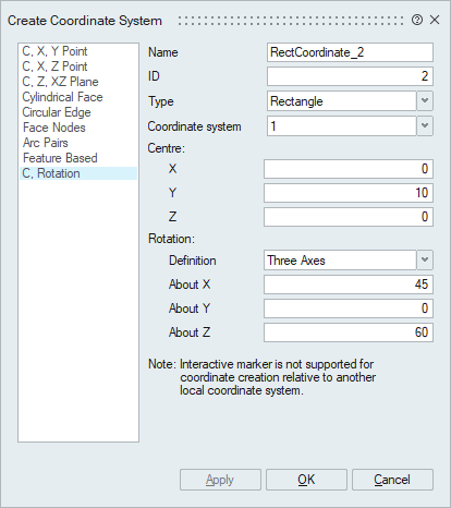
- Centre and Rotation Based Coordinate
The coordinate centre can be defined by specifying the global spatial location. The axes can be defined by specifying the rotation angle with respect to each global axis. Centre and rotation can be defined with respect to Global or any other local coordinate system. The Rotation angles of the axes can be defined by,
- Three axes
- Specify angles for three axes.
- Down Tilt & Azimuth
- Specify Down Tilt (XZ plane) and Azimuth (XY) angles. It is majorly used in High Frequency Electro Magnetic applications.
- Three axes
- In Feature based coordinate creation method, If Axis 1 and Axis 2 are not initially perpendicular based on the selected entities, the definition of Axis 2 is automatically adjusted to "Arbitrary" to enforce a perpendicular orientation between Axis 1 and Axis 2.
-
The Feature based coordinate creation method is supported only for solutions approach.