Far Field
![]()
This type of boundary conditions is used to represent conditions far away from the source of disturbance. The flow at these boundaries are typically uniform. Far-field is generally used for external flows.
Both the inlet and outlet conditions are specified in this panel as the far field can either be an inlet or outlet based on the flow physics.
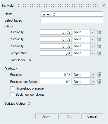
Select faces
The select faces option is used to select the faces to which the far field boundary condition needs to be assigned. Far Field can be applied on faces/face groups of volume meshed bodies.
Inflow
The inflow parameters are specified under the Inflow option to be used if the far field acts as an inlet boundary allowing the fluid to flow into the body.
-
The components of the velocity along the X, Y and Z directions are specified using the respective options under the inflow type. The multiplier functions are used to specify the corresponding time varying X, Y and Z velocity components.
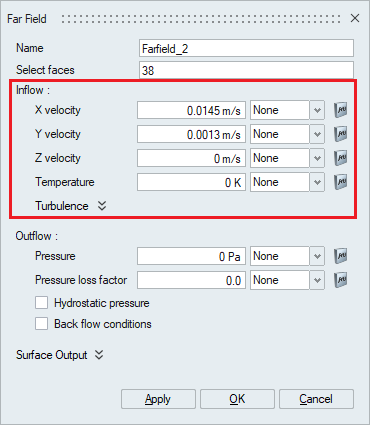
- Temperature
This option is used to define the temperature of the inflow far field boundary condition. The multiplier option is used to scale or specify the time varying inflow temperature values.
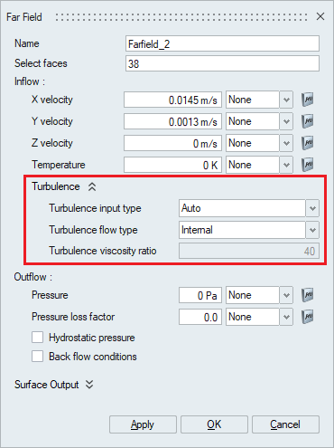
- TurbulenceIf the far field acts as an inlet and the fluid flows into the system, then the turbulence flow parameters need to be define using the Inflow Turbulence option. But this Turbulence options depend on the Turbulence model selected in the Solutions panel. The below options explain the turbulence options available based on the Turbulence model selected.
- Spalart-Allmaras Turbulence modelWhen the turbulence model selected in the Solutions panel is Spalart-Allmaras, various options become available based on the turbulence input type selection.
- Turbulence input type - Auto
When Auto is specified, the solver automatically takes care of the turbulence based on the turbulence flow type. The turbulence flow type is either internal flow or external flow based on the nature of the flow.
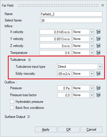
- Turbulence input type – Direct
The second option under turbulence input type is Direct. If this option is selected, the Eddy viscosity value should be specified. The multiplier function can be used to specify a time varying quantity.
- Turbulence input type – Intensity and Length
scale
The third option available under the turbulence input type is the intensity and length scale. This option can be used when the turbulence intensity and the turbulent length scale is known.
Turbulence intensity is defined as the ratio of the standard deviation of the fluctuating flow velocity to the mean flow velocity, and it represents the intensity of the flow velocity fluctuations
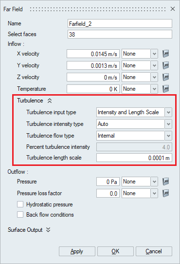
- Turbulence Intensity
type
The turbulence intensity type option is used to specify the turbulence intensity value by either selecting a pre-defined value through choosing Auto, low, medium or high options or by selecting the Value option and typing in the desired intensity value.
- Turbulence Flow
type
When either Auto, low, medium or high option is selected, the turbulence flow type should be specified. The turbulence flow type is either internal flow or external flow based on the nature of the flow.
- Percent Turbulence
Intensity
For Auto turbulence intensity type, the percent turbulence intensity is 4.0% for internal flows and 0.1% for external flows.
For Low turbulence intensity type, the percent turbulence intensity is 1.0% for internal flows and 0.1% for external flows.
For Medium turbulence intensity type, the percent turbulence intensity is 4.0% for internal flows and 0.5% for external flows.
For High turbulence intensity type, the percent turbulence intensity is 10% for internal flows and 1.0% for external flows.
When the Value option is selected, the turbulence intensity value in percentage should be entered under the percent turbulence intensity option.
- Turbulence Length
Scale
Turbulent length scale is a physical quantity describing the size of the large energy-containing eddies in a turbulent flow. The turbulent length scale should normally not be larger than the dimension of the problem and can be specified in the Turbulence Length Scale option.
- Turbulence Intensity
type
- Turbulence input type - Auto
- Other Turbulence ModelsFor other turbulence models, most of the options are similar, except for Turbulence Input Type of Direct. Only this option is discussed below for other turbulence models.
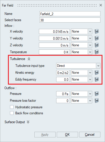
- Shear Stress Transport and K-Omega
- Turbulence Input type – Direct
If this option is selected, the Kinetic energy and Eddy frequency value should be specified. Turbulence kinetic energy is the mean kinetic energy per unit mass associated with eddies in turbulent flow. The multiplier option can be used to specify a time varying quantity.
- Turbulence Input type – Direct
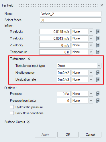
- Realizable K-Epsilon and Standard
K-EpsilonWhen the turbulence model selected in the Solutions panel is Realizable K-Epsilon, various options become available based on the Turbulence Input type selection.
- Turbulence Input type – Direct
The second option under turbulence input type is Direct. If this option is selected, the Kinetic energy and Dissipation Rate value should be specified.
Turbulence kinetic energy is the mean kinetic energy per unit mass associated with eddies in turbulent flow.
The multiplier option can be used to uniformly scale the value or specify a time varying quantity.
- Turbulence Input type – Direct
- Shear Stress Transport and K-Omega
- Spalart-Allmaras Turbulence model
Outflow
The outflow parameters are specified under the Outflow option to be used if the far field acts as an outlet boundary allowing the fluid to flow into the body.
- Pressure
A standard pressure outlet boundary condition is used. The multiplier option is used to specify the time varying pressure values.
- Pressure loss factor
The pressure loss factor is used to specify a coefficient of pressure loss that will be added to or subtracted from the outflow far field boundary condition. The multiplier option is used to uniformly scale or specify the time varying pressure loss factor.
- Hydrostatic pressure
Hydrostatic pressure is the pressure that is exerted by a fluid at equilibrium at a given point within a fluid, due to the force of gravity. This option can be enabled to add the hydrostatic pressure term to the overall pressure boundary condition.
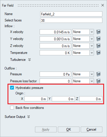
The coordinates of the origin of the body to which this flow boundary condition is assigned should be specified in the X, Y and Z options.
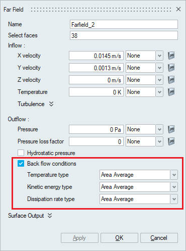
- Back flow conditions
The Back flow conditions must be enabled when there is some flow over a portion of an outflow where the velocity is into the fluid domain. This may lead to instability of the temperature, species, viscoelastic stress, kinetic energy, eddy frequency, and eddy viscosity variables. Enabling back_flow_conditions allows boundary conditions to be specified for these variables only on nodes where there is flow re-entering the domain.
A back flow type of value uses nodal boundary conditions specified by the temperature, species_1,..., species_9, viscoelastic_xx_stress, ..., viscoelastic_zx_stress, kinetic_energy, eddy_frequency, and eddy_viscosity parameters and their corresponding multiplier function parameters. Instead of specifying a value, various solution averages may be used. A back flow type of area_average averages the solution variable over the entire outflow surface and uses the result for the nodal boundary condition.
Surface Output
Surface Output specifies the output parameters for a boundary face.
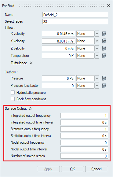
- Integrated output frequency
Time step frequency at which the integrated surface quantities are output. If zero, this option is ignored.
- Integrated output time interval
Time frequency at which the integrated surface quantities are output. If zero, this option is ignored.
- Statistics output frequency
Time step frequency at which the statistics of surface nodal quantities are output. If zero, this option is ignored.
- Statistics output time interval
Time frequency at which the statistics of surface nodal quantities are output. If zero, this option is ignored.
- Nodal output frequency
Time step frequency at which the surface quantities at the nodes of the surface are output. If zero, this option is ignored.
- Nodal output time interval
Time frequency at which the surface quantities at the nodes of the surface are output. If zero, this option is ignored.
- Number of saved states
Number of solution steps to retain on the disk. If zero, all the solution steps are retained.