Crankshaft Meshing: Basic
![]()
Description
This option is uesd to create solid body with Hex/Wedge elements at the journal and pin region. RBE's will be created at the given location inside the solid body.
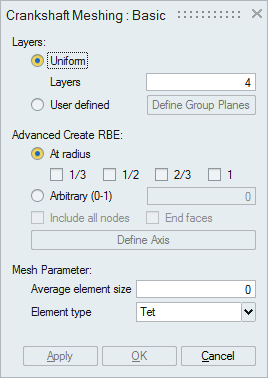
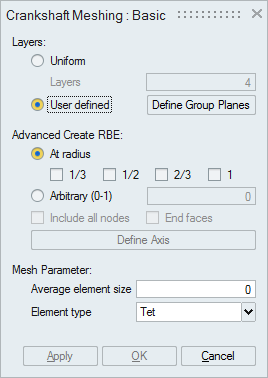
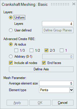
Layers:
- Uniform: Internal disc faces will be created at uniform internal along the axial direction.
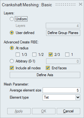
- User defined: Internal disc faces will be created at the user defined location. User can use Define Group Planes to define the location.
Advanced Create RBE:
- At Radius: RBE will be created at 1/3, 1/2,.. of radius of the disc face.
- Arbitrary: RBE will be created based on the given ratio.
- Include all nodes: RBEs will be created for all the nodes within the radius.
- End faces: RBEs will be created for the Journal or Pin end faces. If this option is ON, RBEs will be created at the first and last disc faces.
- Define axis: If axis is defined then the center node of the RBE will lie on this axis.
Internal disc faces and the affected input faces will be remeshed using the given mesh size.
Element type:
Select the desired element type. The desired mesh is obtained based on this selection.
In case of Tet elements, internal faces alone will be created at each layer. User has to do the volume mesh and RBE creation manually.
If there are oil holes present in the crank model, no hex/wedge elements will be created.
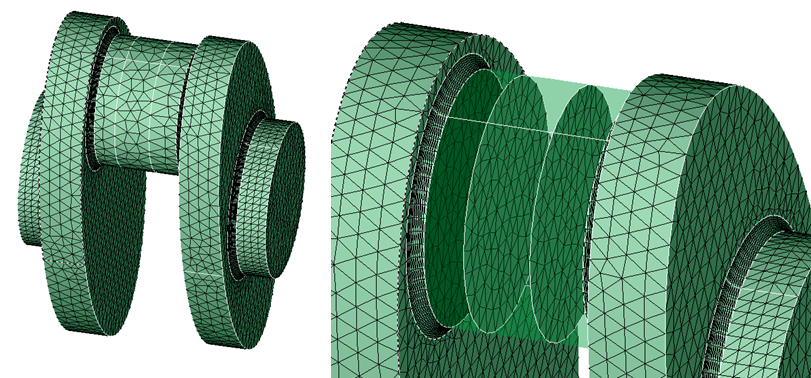
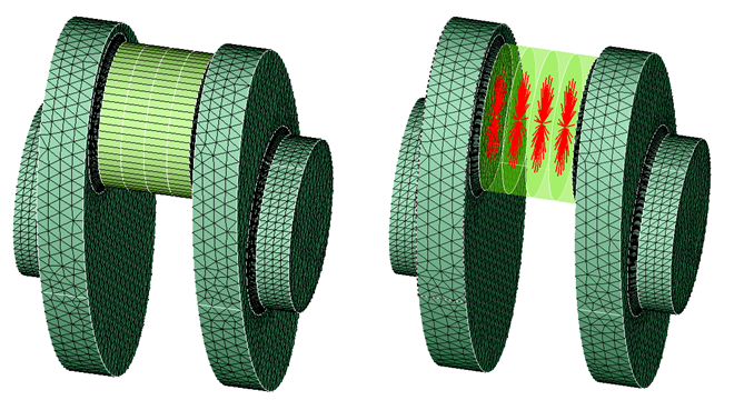
Example 1: Uniform layer with Penta element type
Input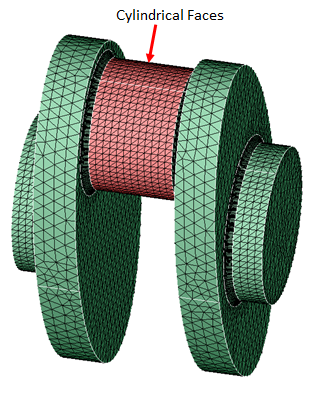
Output
Example: User defined layers with Tet element type
Input
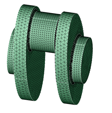
Output