Model Crank Bay
![]()
Model Crank Bay
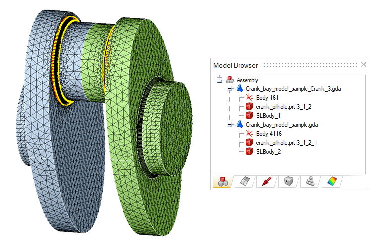
This option is used to incorporate the crank fillet on the crank. Each crank and the corresponding sub model will be added to a new model. Crank will be cut based on the cut location option.
Crank Fillet Info:
- Cylindrical Face/Group: Crank fillet will be created and incorporated at both ends of the cylindrical faces/group.
- Sub Model Profile (XML Format): The xml file contains the definition of the crank fillet. This should be created using "Crank fillet" option (Advanced | Crank Train | Crank Fillet).
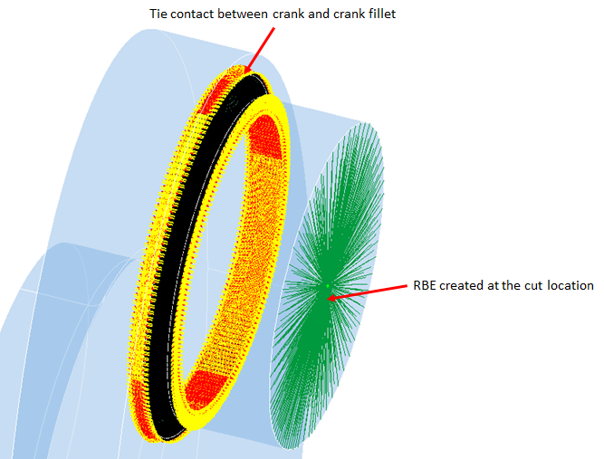
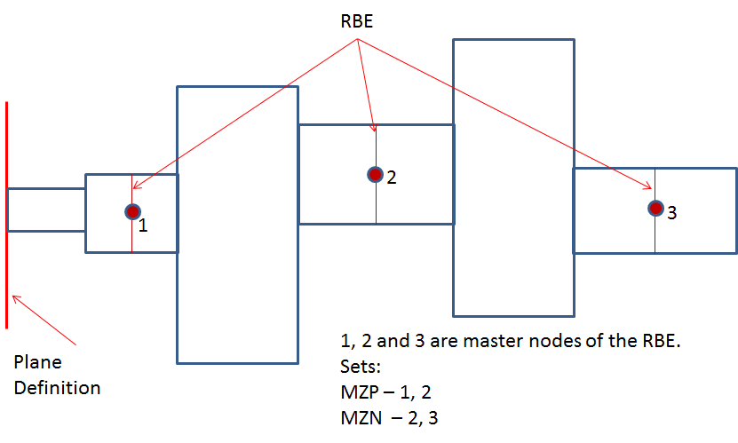
- Cut Location: This option is used to specify the location where the journal
faces cut by plane to create an internal face. RBE element is created using the nodes
of the internal face. Two node sets named MZN and MZP will be created using the
center node of the RBE element at each side of the web.
- No Cut: No internal face is created.
- Center: Internal face will be created at the middle of the journal faces.
- 1/4th From Both ends: Two internal faces will be created at 1/4th distance from both ends of the journal faces.
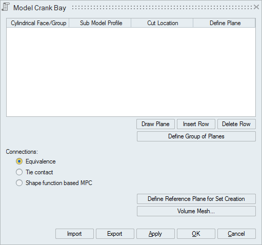
- User Defined Plane: User can define a single plane or multiple planes along the journal faces to create internal faces. Planes can be defined using the "Define Plane" button.
- Draw Plane: This option is used to visualize the user defined plane location.
- Insert Row: Adds a new row to the table.
- Delete Row: Deletes the selected row from the table.
Define group of planes:
This option is used to specify the location where the journal or pin faces cut by plane to create an internal faces. RBE element is created using the nodes of the internal face. Two node sets named MZN and MZP will be created using the center node of the RBE element.
Connections:
Connection between crank fillet and the crank can be achieved using any one of the following methods.
- Equivalence
- Tie Contact
- Shape function based MPC
MZN and MZP nodes sets will be created using the RBE center nodes.
- Define Reference Plane for Set Creation: Plane definition is used to
arrange the RBE center nodes.
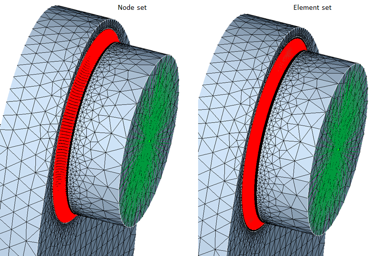
Node and element sets:
Node and elements sets are created using nodes, elements in the crank fillet.
Example
Input xml file name is ModelCrankBaySpecExImage2.xml and input model file name is ModelCrankBayExImage2.slb
Input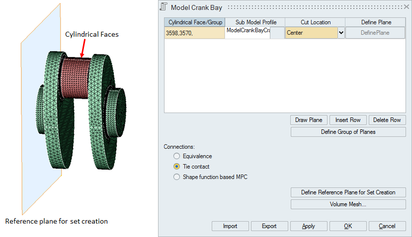
Output