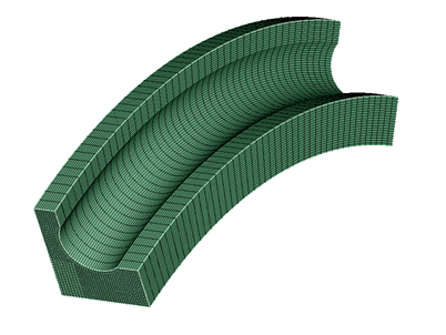
Crank Fillet
![]()
Description
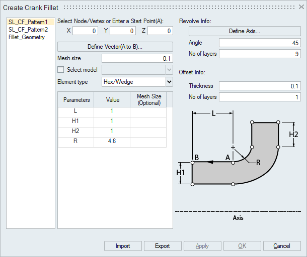
This option is used to create different fillet patterns of Hex or Tet elements.
Start Point(A):X, Y and Z coordinates defines the start point of the profile. User can select a node or vertex or manually enter the values.
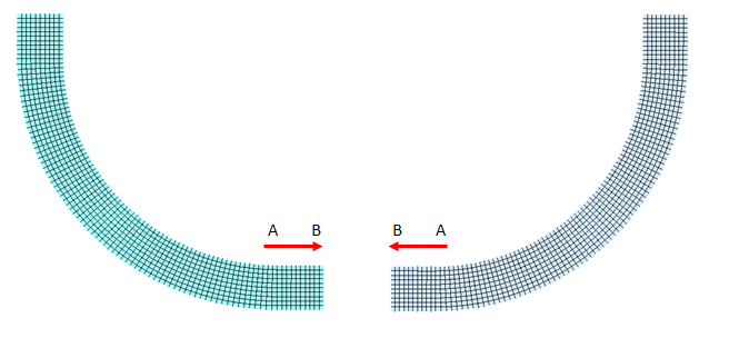
Define Vector (A to B):
Vector A to B defines the direction in which profile will be created.
Mesh Size:
Average element size required to mesh the profile. For few parameters, the mesh size can be specified locally. If no mesh size is given for the parameters, the global mesh size will be used.Select Model:
If this toggle is ON, the crank fillet body will be added to the selected model.
Element Type:
Select the desired element type. The desired mesh is obtained based on this selection.
Revolve Info:
- Define Axis: Defines the axis of revolution through which the profile has to be revolved.
- Angle: Defines the angle of revolution. Revolution will happen on both sides of the profile plane. If the angle of revolution is 90 deg, then the revolution on each side will be 45 deg.
- No of Layers: Number of layers required along the circumference of the profile.
Offset Info:
This is used for creating 100% Hex elements for certain thickness along the fillet surface for the user give Thickness and No of layers.
Import/Export Spec:
Crank fillet definition can be exported or imported as an xml file.
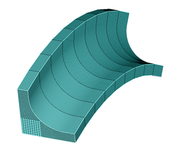
Example: SL_CF_Pattern1
Input xml file name is CreateCrankFilletExImage3.xml and input model file name is CreateCrankFilletExImage2.slb
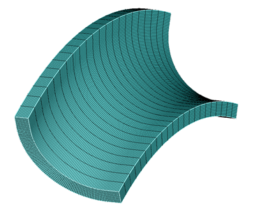
Example: SL_CF_Pattern2
Input xml file name is CreateCrankFilletExImage4.xml and input model file name is CreateCrankFilletExImage2.slb
Example: Fillet_Geometry
Input xml file name is CreateCrankFilletExImage5.xml and input model file name is CreateCrankFilletExImage2.slb