Import Bolt
![]()
Introduction
1D bolts can be created by importing bolt definition file. There are three blocks in this file called BOLT, HEAD_DEF and THREAD_DEF to define bolt, head and thread respectively. Lines that start with # are comment line. The file can have many of these blocks to define bolts between different bodies. Each BOLT definition block should refer to a head and thread definition.
Sample bolt definition file: 1D bolt definition fileIdentifying bolt holes
When bolt definition file is imported, the following steps are carried out to identify the bolt holes and create rigids and bars.
- The contact faces between the head and thread body are identified based on the
value defined by "GAP" in bolt definition file.
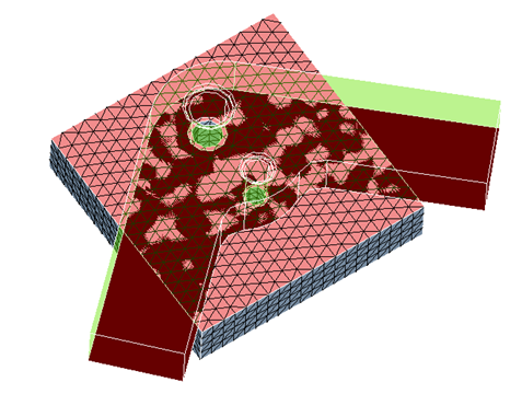
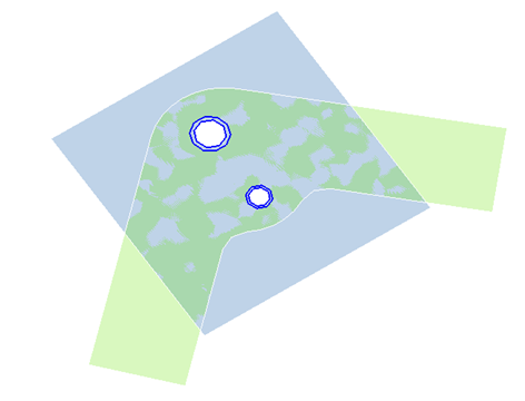
- The circles on these faces within the diameter range from "MIN_DIA" to "MAX_DIA"
will be considered as bolt holes to create rigids. "MIN_DIA" to "MAX_DIA" are
defined in bolt definition.
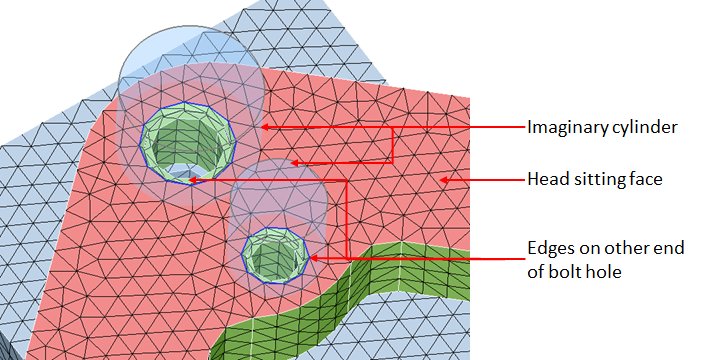
- The edges on other end of holes of head body is identified by considering an
imaginary cylinder coaxial to the bolt hole. Diameter of the imaginary cylinder =
"TOP_RBE_SCALE" x diameter of bolt hole. There is also a keyword "BOLT_HEAD_DIA"
to define the diameter of bolt head. If this keyword is defined, then the diameter
of imaginary cylinder will be diameter of bolt head. The faces which are
intersecting with imaginary cylinder are assumed as bolt head sitting faces. The
edge loop nearest to the circumference of imaginary cylinder is assumed as edges
on end of bolt hole.
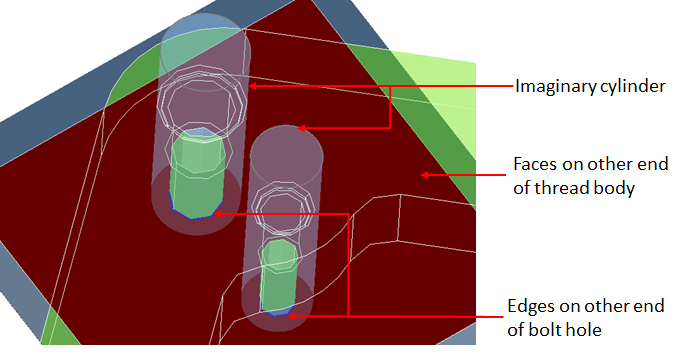
- The edges on other end of holes of thread body is identified by considering an
imaginary cylinder coaxial to the bolt hole. Diameter of the imaginary cylinder =
"BTM_RBE_SCALE" x diameter of bolt hole. There is also a keyword "NUT_DIA" to
define the diameter of nut. If this keyword is defined, then the diameter of
imaginary cylinder will be diameter of nut. The faces which are intersecting with
imaginary cylinder are assumed as the faces at other end of bolt hole. The edge
loop nearest to the circumference of imaginary cylinder is assumed as edges on end
of bolt hole.
Bolt definition
BOLT - Keyword to define bolt
| Keyword | Value | Description |
|---|---|---|
| BOLT_NAME | Name of bolt definition | |
| METHOD | CIRCLE_BASED/CYLINDER_BASED | Method to identify bolt CIRCLE_BASED - Bolt holes between head and thread body is identified based on circular edge loops in contact faces. CYLINDER_BASED - Matching bolt holes between head and thread body is identified based on matching cylinders. |
| HEAD_ENTITY | Name of head body | |
| THREAD_ENTITY | Name of thread body. | |
| GAP | Gap between the contact faces of head and thread body. | |
| HEAD_DEF_NAME | Name of head definition. | |
| THREAD_DEF_NAME | Name of thread definition. | |
| AXIS_INCLINATION_TOL | Tolerance for axis inclination to identify matching bolt holes (Angle in degrees). | |
| AXIS_SHIFT_TOL | Tolerance for axis shift to identify matching bolt holes. | |
| MIN_DIA | Minimum diameter of bolt holes. | |
| MAX_DIA | Maximum diameter of bolt holes. | |
| CONNECTION | EQUIVALENCE/RBAR/MPC/PRETENSION | Type of connection between head and thread. EQUIVALENCE - End node of bar and/or master node of RBE between head and thread will be equivalenced. RBAR - RBAR will be created between end node of bar and/or master node of RBE between head and thread. MPC - MPC will be created between end node of bar and/or master node of RBE between head and thread. Keyword "ENFORCED_DISP" defines enforced displacement along the axial direction of bolt. PRETENSION - Creates pretension force between head and thread. The additional keywords to define bar pretension under bolt definition are
|
| ENFORCED_DISP | Enforced displacement along the axis of bolt for MPC connection. | |
| PRETENSION_FORCE | Value for pretension force. | |
| LOCK | true/false | Lock option for bolt. true - Bolt will be locked for pretension. false -Bolt will be unlocked for pretension. |
| BOLT_TYPE | THREADED/THROUGH | Type of bolt. THREADED - Blind threaded hole. THROUGH - Through hole. |
| NUMBER_OF_BARS | Number of bar elements between head and thread RBE. |
Keywords BOLT_NAME, HEAD_ENTITY, THREAD _ENTITY, GAP, HEAD_DEF_NAME, THREAD_DEF_NAME, AXIS_INCLINATION_TOL AXIS_SHIFT_TOL MIN_DIA, MAX_DIA, and PRETENSION_TYPE are mandatory. If anyone on this keyword is missing or not defined correctly, then that definition will be invalid. If other keywords are not defined/missed, default value will be assumed. The default value for each keyword is
METHOD = CIRCLE_BASED
CONNECTION = EQUIVALENCE
ENFORCED_DISP = 1.0
PRETENSION_FORCE = 100.00
LOCK = false
NUMBER_OF_BARS = 3
Head definition
HEAD_DEF - Keyword to define head
| Keyword | Value | Description |
|---|---|---|
| NAME | Name of head definition. | |
| TYPE | 1/2/3/4/5/6/7/8/9/10/11 | Type of bolt.
|
| TOP_RBE_SCALE | An imaginary cylinder coaxial to the bolt hole is assumed. Diameter of this imaginary cylinder = "TOP_RBE_SCALE" x diameter of bolt hole. Nodes on bolt head sitting faces and inside this imaginary cylinder are the slave nodes for top RBE. | |
| BTM_RBE_SCALE | An imaginary cylinder coaxial to the bolt hole is assumed. Diameter of this imaginary cylinder = "BTM_RBE_SCALE" x diameter of bolt hole. Nodes on contact faces and inside this imaginary cylinder are the slave nodes for bottom RBE. | |
| UNIFORM_TOP_RBE_DIA | Instead of defining the scale factor for top RBE, an uniform diameter can be defined for all bolt holes. If this keyword is defined, an imaginary cylinder of this diameter will be assumed for all bolt holes. | |
| UNIFORM_BTM_RBE_DIA | Similarly an uniform diameter can be defined for bottom RBE. | |
| BOLT_HEAD_DIA | An imaginary cylinder of this diameter and coaxial to the bolt hole is assumed to find the other end of the bolt hole. | |
| INCLUDE_SOLID_NODES | YES/NO | Option to include solid nodes. YES - Include solid nodes. NO - Will not consider solid nodes. |
| DIA_FOR_SOLID_NODES | Diameter to identify solid nodes. | |
| TOP_RBE_SLAVE_NODE_TYPE | EDGE_NODE/FACE_OVERLAP_NODE/DEFAULT | Option for slave nodes for top RBE. EDGE_NODE - Nodes on edges of bolt hole are slave nodes for RBE. FACE_OVERLAP_NODE - Overlapping nodes on contact faces are slave nodes for RBE. DEFAULT - Nodes inside the imaginary cylinder based on the scale/diameter. |
| BTM_RBE_SLAVE_NODE_TYPE | EDGE_NODE/FACE_OVERLAP_NODE/DEFAULT | Option for slave nodes for bottom RBE. |
| PLANARITY_TOL | Planarity tolerance to identify nodes on contact faces and bolt-head sitting faces (Angle in degrees). | |
| BAR_DIA | Diameter of bar. | |
| BAR_MATERIAL | Material for bar. |
Keywords NAME, TYPE are mandatory. If anyone on this keyword is missing or not defined correctly, then that definition< will be invalid. If other keywords are not defined/missed default value will be assumed. The default value for each keyword is
TOP_RBE_SCALE = 1.5
BTM_RBE_SCALE = 1.5
INCLUDE_SOLID_NODES = NO
TOP_RBE_SLAVE_NODE_TYPE = DEFAULT
BTM_RBE_SLAVE_NODE_TYPE = DEFAULT
PLANARITY_TOL = 20.0
BAR_DIA = 1.0
BAR_MATERIAL = Default material
Thread definition
THREAD_DEF - Keyword to define thread
| Keyword | Value | Description |
|---|---|---|
| NAME | Name of thread definition. | |
| TYPE | 1/2/3/4/5/6/7 | Type.
|
| TOP_RBE_SCALE | An imaginary cylinder coaxial to the bolt hole is assumed. Diameter of this imaginary cylinder = "TOP_RBE_SCALE" x diameter of bolt hole. Nodes on contact faces and inside this imaginary cylinder are the slave nodes for top RBE. | |
| UNIFORM_TOP_RBE_DIA | Instead of defining the scale factor for top RBE, an uniform diameter can be defined for all bolt holes. If this keyword is defined, an imaginary cylinder of this diameter will be assumed for all bolt holes. | |
| NUT_DIA | An imaginary cylinder of this diameter and coaxial to the bolt hole is assumed to find the other end of the bolt hole. | |
| SHAPE | UP/DOWN/BOTH | Shape of bottom RBE. UP - Nodes on threaded faces above the point based on the depth and pitch. DOWN - Nodes on threaded faces below the point based on the depth and pitch. BOTH - Nodes on threaded faces both above and below the point based on the depth and pitch. |
| PITCH | Pitch to identify nodes for bottom RBE. | |
| DEPTH | Depth from the contact face to create bottom RBE. | |
| INCLUDE_SOLID_NODES | YES/NO | Option to include solid nodes. YES - Include solid nodes. NO - Will not consider solid nodes. |
| DIA_FOR_SOLID_NODES | Diameter to identify solid nodes. | |
| TOP_RBE_SLAVE_NODE_TYPE | EDGE_NODE/FACE_OVERLAP_NODE/DEFAULT | Option for slave nodes for top RBE. EDGE_NODE - Nodes on edges of bolt hole are slave nodes for RBE. FACE_OVERLAP_NODE - Overlapping nodes on contact faces are slave nodes for RBE. DEFAULT - Nodes inside the imaginary cylinder based on the scale/diameter. |
| PLANARITY_TOL | Planarity tolerance to identify nodes on contact and bolt-head sitting faces (Angle in degrees). | |
| BAR_DIA | Diameter of bar. | |
| BAR_MATERIAL | Material for bar. |
Keywords NAME, TYPE, PITCH and DEPTH are mandatory. If anyone on this keyword is missing or not defined correctly, then that definition will be invalid. If other keywords are not defined/missed, default value will be assumed. The default value for each keyword is
TOP_RBE_SCALE = 1.5
SHAPE = DOWN
INCLUDE_SOLID_NODES = NO
TOP_RBE_SLAVE_NODE_TYPE = DEFAULT
PLANARITY_TOL = 20.0
BAR_DIA = 1.0
BAR_MATERIAL = Default material