Model Definition Language (MDL) and Systems
Tutorial Level: Intermediate In this tutorial, you will learn how to work with the Model Definition Language (MDL), MotionView's language for its models and definitions and the System entity.
Introduction
- Edit in any text editor.
- It assists with model debugging.
- Use conditional statements "if" for custom modeling requirements.
- Build modular and reusable models.
- Parameterize the models and use modeling entities which are not available through the graphical user interface.
- Build a library and automate model building.
About this Tutorial
- MDL syntax
- Concepts of system
- Attachments and properties
- Working with systems through the graphical user interface
- Definition and Data
- Using parametric expressions
- Alter the length and orientation of the link.
- Change attaching bodies.
- Be reusable to create multiple links.

- A Body and a Graphic defined using two points.
- A joint connecting the Link body and another attaching body.
- Properties to control the length and angle of orientation of the link.
- Parametric relation of one end point to the other end point.
Systems
A system entity defines a collection of modeling entities. A model can be organized into different systems. Examples of system entities include SLA suspension system, wiper blade system, and power-train system. Systems can be hierarchical in nature (for example, a system can be a child of another system).
Create a Link System Using the Graphical User Interface
Create a System Instance
- Launch a MotionView session.
-
Open the Add System dialog in one of the following
ways:
- In the Model Browser, right-click on Model and select . In the dialog, select the System option and click Next.
- From the Assembly ribbon, click the
System icon
 .
.
- In the Add System dialog, specify the Variable as sys_link, the Label as Link System, and the Definition Name as def_sys_link.
-
Click OK.
A system
 is added to the model.
Add Points to the System
In this step you will add three points to the Link System.
- In the Model Browser, click Link System.
-
Invoke the Points guide bar in one of the following
ways:
- From the Model Browser, right-click on Link System and select .
- On the Geometry ribbon, click the
Points icon
 (single point icon at the top right
corner).
(single point icon at the top right
corner).
- Click anywhere in the modeling window to create a point.
- Specify the point’s coordinates as X=0, Y=0, Z=0.
-
From the Entity Editor, specify the
Label as Link Origin and the
Varname as p_origin.
Note: The Entity Editor can be turned on from the View menu.
- Click anywhere in the modeling window to create a second point.
- Specify the Label as Link End and the Varname as p_end.
-
In the Properties section of the Entity Editor, click the Z coordinate
field, and then click the
 button.
This will display the Expression Builder.
button.
This will display the Expression Builder. - Delete the value from the Expression area (located at the top of the dialog).
- From the Model Tree (center of the dialog), expand the Link System - Points - Link Origin folders and select the z data member.
-
Click the Add button.
Figure 2. Define point's Z coordinate using the Origin Point 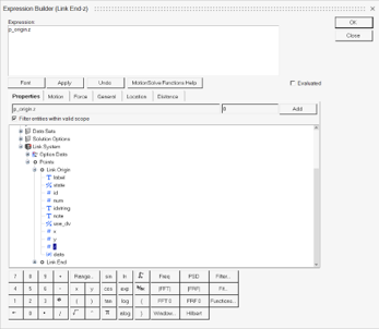
The expression p_origin.z is added into the Expression area. -
Add -100 to the expression.
Figure 3. Define point’s z coordinate parametrically 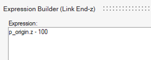
-
Select the Evaluated check box located at the bottom
right corner of the Expression area.
The Expression area now displays the evaluated value of the expression.
-
Click OK to close the
dialog.
Through the above steps the Z coordinate of Link End has been parametrically linked with regard to the Z coordinate of the Link Origin. It is placed at a distance of 100 length units.
-
Repeat steps 9 through
14 for the X and Y
coordinates. Choose the x and y data member respectively in Step 10.
-
For the Y coordinate, specify the expression as
p_origin.y-100.
Figure 4. Point’s coordinates defined using parametric expressions 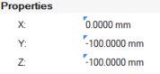
Note: You can also add the X and Y coordinate expressions by copying the Z coordinate fields in the Entity Editor and editing it. The blue arrow appears for parametric expressions.
-
For the Y coordinate, specify the expression as
p_origin.y-100.
- Click anywhere in the modeling window to create a third point.
-
From the Entity Editor, specify the
Label as Link CG and the
Varname as p_CG.
This point will be positioned between p_origin and p_end.
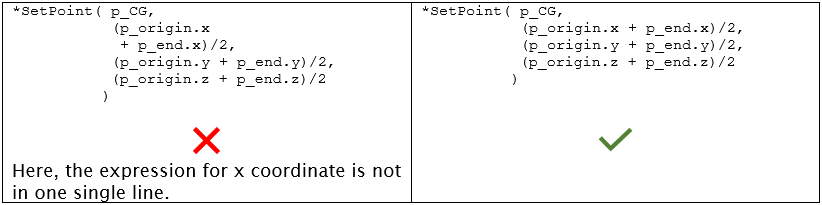
-
Click the X coordinate field and enter the following
expression:
(p_origin.x + p_end.x)/2. -
Repeat step 18 for the
Y and Z coordinates.
-
For the Y coordinate, specify the expression as:
(p_origin.y + p_end.y)/2. -
For the Z coordinate, specify the expression as:
(
p_origin.z + p_end.z)/2.
-
For the Y coordinate, specify the expression as:
-
Right-click in an empty space and click the green check
 to exit the Points context. Fit the view (using the
‘F’ key).
to exit the Points context. Fit the view (using the
‘F’ key).
Add a Body to the System
In this step you will add a body to the Link System.
- In the Model Browser, click Link System.
-
To add a body, enter the Bodies context in one of the following ways:
- Right-click on Link System and select .
- On the Geometry ribbon, click the Bodies icon
 .
.
A guide bar appears.Click the Create and Exit icon
 to create the Body and exit the guide bar.
 - Select the added body in the Model Browser. In the Entity Editor, change the Label and Varname of the body to Link Body and b_link respectively.
-
In the Properties section:
- Clear the Derive From Graphics check box.
- Specify the Mass as 1, and the Ixx, Iyy, and Izz Inertia properties as 50.
Figure 5. Body's inertia properties 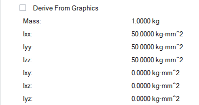
- In the CM Coordinate System section, select the User-defined option.
-
Define the body’s CM location, in one of the following ways:
- Click on the Origin collector and select the Link CG point from the modeling window.
- Double-click on the Origin Advanced selector
 , select Link CG in the
dialog and click OK.
, select Link CG in the
dialog and click OK.Figure 6. Define Body's CM location 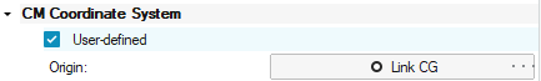
Add Graphics to the System
-
In the Model Browser, click Link
System.
Note: If any child entity is currently selected, this step is not required.
-
Open the Cylinder graphic guide bar in one of the
following ways:
- Right-click on Pendulum and select .
- On the Geometry ribbon, click the
Primitive icon
 and select the Cylinder
icon
and select the Cylinder
icon  in the secondary ribbon that appears.
- In the guide bar, clear the Create Body option check box.
-
Define the graphic’s Body in one of the following
ways:
- Use the Body collector to select the Link Body directly from the modeling window.
- Double-click on the Body Advanced selector (next to the Body collector in the guide bar), and select the Link
Body from the dialog.
-
Define the graphic’s Origin in one of the following
ways:
- Use the Origin collector to select the Link Origin point directly from the modeling window.
- Double-click on the Point Advanced selector
, and select the Link
Origin from the dialog.
-
Click Create
 , to add the graphic to the system.
- In the microdialog that appears (or the Properties section in Entity Editor), enter 5 for Radius 1 and hit Enter.
- From the Entity Editor, in the General section, specify the Label as Link Graphic and the Varname as gcyl_link.
-
To orient the graphic:
- From the Align Method drop-down menu, select Point.
-
Select Link End for the Point either from the
modeling window or using the Advanced
selector .
-
Select the Autolength option under the Properties
section.
This option sets the graphics’ length as the distance between Origin point and the Align Point.
-
Click Finished Editing
to exit the dialog.
Figure 7. Orient the cylinder graphic 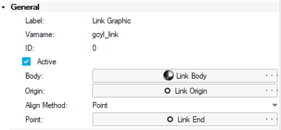
-
Click
 on the guide bar to exit the
Graphics context.
on the guide bar to exit the
Graphics context.
-
Save the model
 to your <working directory>
as link_gui.mdl.
to your <working directory>
as link_gui.mdl.
Add a Joint to the Link System
In this step you will add a revolute joint on the link body.
- In the Model Browser, click Link System.
-
Open the Joints guide bar in one of the
following ways:
- Right-click on Link System and select .
- On the Model ribbon, click the
Joints icon
 .
.
- Select Link Body for Body 1.
- Select Ground Body for Body 2.
- Select Link Origin as the Origin.
-
Click Create
, to add the joint to the Model Browser.
- In the Entity Editor that appears, for Label enter Pivot, for Variable enter j_pivot, and for Type select Revolute Joint.
- From the Orientation section, use the Method drop-down menu to change the collector to Vector.
-
Double-click on the Vector Advanced selector and select Global X.
-
Click Cancel
 to exit the guide bar.
Run the Model
-
From the Analyze ribbon, click the Quick
Start/Stop Motion Analysis icon
 located under the Run group.
The link should oscillate like a pendulum under gravity.
located under the Run group.
The link should oscillate like a pendulum under gravity. -
Exit the results animation mode by toggling the Review run
results icon
 .
.
-
Save the model .
Review the MDL
- Open the link_gui.mdl file that was just saved in the text editor.
-
Below the initial header, the file would look as follows:
*BeginMDL( the_model, "Model", "2025.0.0.6" )

  *StandardInclude(FILE)
  *SetCurrentSolverMode(MotionSolve)
  *System( sys_link, "Link System", def_sys_link )
  *DefineSystem( def_sys_link )
    *Point( p_origin, "Link Origin" )
    *Point( p_end, "Link End" )
    *Point( p_CG, "Link CG" )
    *Body( b_link, "Link Body", p_CG, , , ,  )
    *Graphic( gcyl_link, "Link Graphic", CYLINDER, b_link, p_origin, POINT, p_end, 5, gcyl_link.r1, , 0.0, CAPBOTH, 3 )
    *RevJoint( j_pivot, "Pivot", b_link, MODEL.B_Ground, p_origin, VECTOR, MODEL.V_Global_X, ALLOW_COMPLIANCE )
  *EndDefine()

  *BeginContext( sys_link )
    *SetPoint( p_origin,      0, 0, 0 )
    *SetPoint( p_CG,          (p_origin.x + p_end.x)/2, (p_origin.y + p_end.y)/2, (p_origin.z + p_end.z)/2 )
    *SetPoint( p_end,         p_origin.x, p_origin.y-100, p_origin.z-100 )
    *Set( b_link.inertia_props_from_graphic, false )
    *SetBodyInertia( b_link,          1, 50, 50, 50 )
    *Set( b_link.usecm, true )
    *Set( j_pivot.isbush, false )
  *EndContext()
*EndMDL()
- MDL File Overview
-
- All statements in a model are contained within a *BeginMDL() - *EndMDL() block.
- The syntax of the MDL statement begins with an asterisk (*) followed by a valid entity statement with its arguments defined.
- Statements without a leading asterisk (*) are considered
comments.Note: The comments are not read in by the MotionView graphical user interface and are removed if the model MDL is saved back or saved to a different file.
- MDL accepts statements in any order, with a few exceptions. The graphical interface does not necessarily maintain the same order when saved.
- The indentation and spaces, though not required, improves readability.
- A statement can be spread in multiple lines, provided an argument
should be within the same line. That is, any string/expression
between two commas should be in the same line. For example:
In general, the mdl file follows the following structure://comments about the MDL file *BeginMDL(…) //Topology section *Point… *Body… *System(…) // definitions sub-section *DefineSystem(..)… *Point... *Point... *EndDefine() //Property of entities directly in BeginMDL() *SetPoint(…) //Property section for entities within Systems and analysis *BeginContext() *SetPoint(…) *SetBody(…) .. *EndContext() . *EndMDL() - Entities in MDL
- There are two types of entities:
- General Entities
- Definition Based Entities
- General Entities
-
- Have one statement to define the entity. They may have one or more
statements to set their properties. For example:
- *Point() defines a point. *SetPoint() sets the properties for the point.
- *Body() defines a body. *SetBody()/*SetBodyInertia() sets the mass and inertia and *SetBodyIC() sets the initial conditions for the body.
- Each entity is defined using a variable name (varname for short) and is always the first argument in the MDL statement for an entity. The variable name is a unique identifier for the entity and all properties and references to the entity are set using the variable name.
- All entities have certain common properties. For example label, state, and varname (variable name).
- Each general entity has specific properties consistent with its type. For example, a point has the properties x-coordinate, y-coordinate, z-coordinate. A body has properties mass, Ixx, Iyy, and so on.
- Have one statement to define the entity. They may have one or more
statements to set their properties. For example:
- Definition Based Entities
-
- Are defined through a block statement, called definition, and its instance is created in a model by an instantiation statement.
- The block generally begins with a *Define()
statement and end with a *EndDefine() statement.
For example:
- *DefineSystem() - *EndDefine() defines a system. *System() creates an instance of a definition.
- In the current work, def_sys_link is a system definition, and an instance sys_link uses this definition.
- The entity (or block) is comprised of a series of other MDL entities or members.
- These entities are reusable. Once defined, the same entity-definition may be instantiated several times within the same model.
- Some of the commonly used defined-based entities are outlined in the
table below:
Entity Description System A system entity defines a collection of modeling entities. These definitions may be used repeatedly within the same model or different MDL model files. A model can be organized into different systems. Systems can be hierarchical in nature (for example, a system can be a child of another system). Assembly An assembly is similar to a system entity, except that the definition and data resides in separate files than the model file. Analysis An analysis is also similar to a system. It is a collection of entities (bodies, joints, and so on) describing a particular analysis task or event applied to a model. For example, a static ride analysis is one of the analysis that can be applied to a model. An analysis can only be instantiated under Model (the top level root system). A system can be a child of an analysis; however, the reverse is not valid. Dataset A dataset is a collection of user-defined variables of type integer, real, string, Boolean, or filename. These variables can be referred or parameterized to other entity properties. Datasets are displayed in a tabular form, thereby offering a single window to modify a model. Generally, design variables are collectively defined in the form of a dataset. A dataset can be instantiated within a system or an analysis. Template A template is a utility that uses the Templex program in HyperWorks. It can be used to create user-defined calculations and codes embedded into the model. The output of such code can be written out to solver deck or execute another program. Another use is to implement solver statements and commands not supported by MDL and to generate text reports. Note: The system, assembly, and analysis are together referred to as container entities (or simply containers). - Excluding Templates, properties of child entities can be set within a definition. They form default data for those entities.
- Definition blocks within MDL are mutually exclusive and
independently placed, even though their instance could be a child of
another definition.
Figure 8. Correct arrangement for definitions 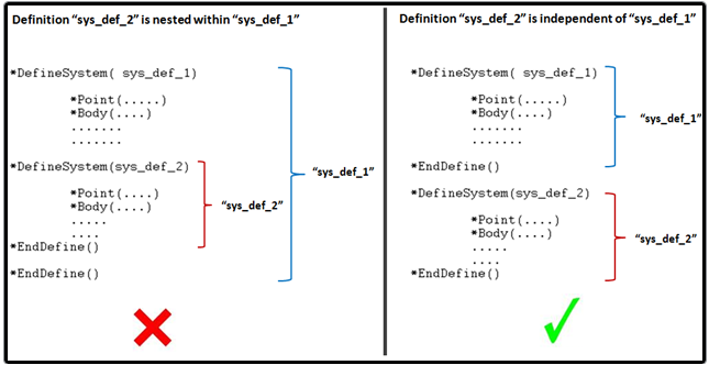
- BeginContexts blocks (which sets data for the systems/datasets) are nested.
Add Attachments
- Attachments are objects within a definition that refer to objects external to the definition.
- Attachments are like local variables in a function or a program.
- Using attachments makes the system modular and reusable both within the same model as well as in a different model.
- If an external object is used in several places within a system, referring that object via attachments makes it easier to swap the object with one single change in the attachment.
Create Attachments for the Link System
- In the Model Browser, click Link System.
- In the Entity Editor, from the Attachments section, click on the Add/Delete button.
- In the Attachments dialog, click Add to invoke the Add an Attachment dialog.
- Specify the Label as Attachment Point and the Variable as arg_p. Verify that Type is set to Single only.
- From the drop-down menu, select Point.
- Click OK.
-
Use steps 3 through
6 to create a Body
attachment.
- Specify the Label as Attachment Body and the Variable as arg_b.
- From the drop-down menu, select Body.
-
Close the Attachment dialog.
Figure 9. Attachments Entity Editor 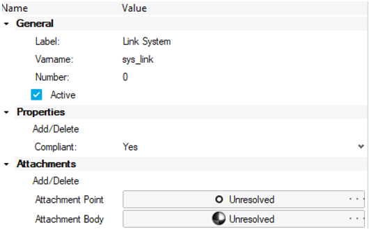
Note: These attachments will be used to attach this system to other model entities. Notice that both are currently Unresolved, meaning they are not yet referring to another entity in the model. - Activate the Attachment Point collector.
- Click in an empty space in the modeling window to pick Global Origin.
- Activate the Attachment Body collector.
- Click in an empty space in the modeling window to pick Ground Body.
Replace Link Origin with Attachment Point
In this step you will replace references to point Link origin (p_origin) with the Attachment Point (arg_p).
- Select the point Link End.
-
In the Entity Editor, edit the expressions in the
properties by replacing p_origin with
arg_p.
The expressions before and after the change are listed below:
Properties Before Change After Change Link End - X p_origin.x arg_p.x Link End - Y p_origin.y-100 arg_p.y-100 Link End - Z p_origin.z-100 arg_p.z-100 -
Similarly replace expressions in the properties of Link
CG.
The expressions before and after the change are listed below:
Properties Before Change After Change Link CG - X (p_origin.x + p_end.x)/2 (arg_p.x + p_end.x)/2 Link CG - Y (p_origin.y + p_end.y)/2 (arg_p.y + p_end.y)/2 Link CG - Z (p_origin.z + p_end.z)/2 (arg_p.z + p_end.z)/2 -
Replace the references in Link Graphic, as well as joint
Pivot.
-
Select Link Graphic. In the property editor,
activate the Origin collector and click on to display up the Advanced selector.
-
In the Select a Point dialog that appears, find the attachment
Attachment Point and click
OK.
Figure 10. Advanced selection for Attachment Point 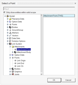
-
Similarly, replace the references Body 2 and
Origin in the joint
Pivot to the Attachment
Body and Attachment Point
respectively.
Figure 11. Joint Pivot Entity Editor 
Note: Observe a blue tick at the top left corner of the collectors. A blue tick on a collector indicates an indirect reference such as an attachment or an attribute of another entity. -
Select Link Graphic. In the property editor,
activate the Origin collector and click on
Add Length and Angle Properties
Add Properties to the System - Length and Angle
In this step you will add properties to the system – Length (L) and angle (a) so that the length and orientation of the link can be controlled at the system level.
- In the Model Browser, click Link System.
- In the Entity Editor, from the Properties section, click on the Add/Delete button.
- In the Datamember dialog, click Add to invoke the Add new user data entry dialog.
- From the drop-down menu, select Real for Type.
- Specify the Variable as L and the Label as Length (mm).
- Click Apply.
- Create a second property with the Variable as a and Label as Angle(radians). Click OK and close the Datamember dialog.
-
In the Link System
Entity Editor, from the Properties section, specify the
Length value as 100 and the
Angle value as 30d.
Note: The ‘d’ in “30d” sets the value equivalent to 30 degrees in radians.
Figure 12. System Entity Editor 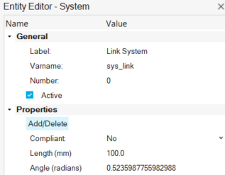
Define the Link End Point Distance and Angle from the Link Origin
In this step you will change the Link End point expression to define the point at distance (L) and at angle (a) from the Link Origin using sin and cos functions.
- In the Model Browser, click Link System - Points - Link End.
-
In the Entity Editor, from the
Properties section, click the
Y coordinate field. Then click on to display the Expression Builder.
- Delete 100 from arg_p.y-100.
- From the Model Tree expand Link System – Real Data – Length (mm) and select the value data member.
- Click the Add button.
- Add *cos() to the expression after L.value and set the cursor in between the parentheses of the cos function.
-
As in step 4, find the Angle (radians) datamember and
add it to the expression.
The expression should look as follows:
Figure 13. Define Link End's Y coordinate using the Origin Point and cos function 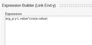
- Select the check box to verify that the expression is valid and returns a value of -86.6025.
- Click OK to close the Expression Builder.
- Similarly, set the value for the Z coordinate to expression arg_p.z-L.value*sin(a.value) which evaluates to -50.0000.
-
Test the system.
- Select Link System and from the Entity Editor change the values for length and angle.
The points and graphics are updated accordingly. - Save the model.
Add Another Link System
- In the Model Browser, select the Link System.
- In the Entity Editor, change its Label to Link System 1 and Varname to sys_link1.
-
Right-click and select Copy (or use the shortcut
Ctrl+C).
Figure 14. Copy system 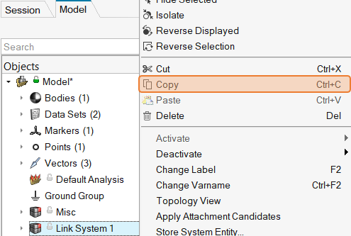
-
Select the top-level Model system, right-click and
select Paste (or use Ctrl + V).
Figure 15. Paste system 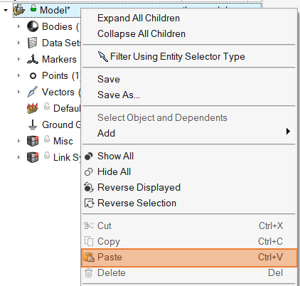
An instance System 0 (varname sys_0) is created. -
In the Entity Editor, set the following:
- Label to Link System 2.
- Varname to sys_link2.
- Length to 150.0.
- Angle to 15d.
- Attachment Point to Link End (under Link System 1).
- Attachment Body to Link Body (under Link System 1).
The model should look as follows:Figure 16. Model after adding the second link system 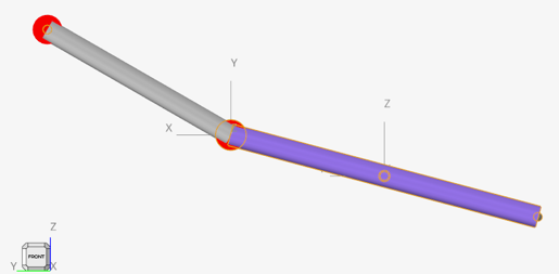
-
Save the model.
Observe the icons next to the systems in the Model Browser. There is a ‘hand’ below the regular system icon. The hand indicates that the entity is sharing definition with another entity.
Figure 17. Shared system icons 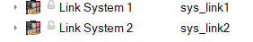
- Open the saved model MDL file in the text editor.
-
Observe the two *System statements. Both refer to the
definition def_sys_link.
Figure 18. System instances in the MDL file 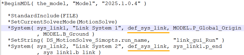
- When a definition-based entity is copied within a model, both instances share the definition.
- Any change like adding or deleting an entity to either of the instances, modifies the definition and the linkage (sharing) is broken. This behavior can be controlled through the option Break shared instance when modified from .
- A change in the properties of any entities (except Graphics) does not change the definition or any sharing.
Export and Import the System
Any system definition can be saved into a separate file through export.
Export the System Definition
In this step you will learn how to export your system definition to your <working directory>.
- In the Model Browser, click Link System 1.
- From the Menu bar, click to invoke the Export Definition dialog.
-
In the System collector make sure Link System
1 is selected.
If not, use the System collector to invoke the Select a System dialog and make your selection.
Figure 19. Exporting the system definition 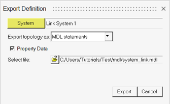
-
Click the
 (file browser) and browse to your
<working directory>.
(file browser) and browse to your
<working directory>.
- Specify the name of the file as sys_link.mdl and click Save.
- Click Export.
-
Review the file system_link.mdl in a text editor.
It will contain only the definition block.
Import the System Definition
In this step you will learn how to instantiate a system definition through import.
- In the Model Browser, select the Model system.
- From the Menu bar, click to invoke the Import Definition dialog.
-
In the System collector make sure
Model is selected.
If not, use the System collector to invoke the Select a System dialog and make your selection.
-
Click the (file browser) and browse to your
<working directory>.
- Select the sys_link_gui.mdl file and click Open.
- In the dialog, select def_sys_link.
-
Change the Label to Link System 3
and the Variable to
sys_link_3.
Figure 20. Importing the Pendulum system 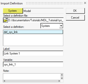
-
Click OK.
This will instantiate the definition. Link System 3 will appear in the Model Browser.
- Click on Link System 3.
-
In the Attachments section, resolve the Attachment Point
and Body to point Link End and
Body Link Body respectively under Link
System 2.
Note: If using the Advanced selector and Link System 2 is not visible, make sure that the Only show entities with valid scope option check box is cleared.
Figure 21. Advanced selector dialog 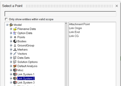
-
Save the model .
-
Right-click on the header of the Model Browser and select
the Definition column.
Figure 22. Select the Definition column 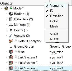
-
Observe the Definition name of the systems. Link System
3 has a different definition name.
Note: MotionView renames the definition when imported if another definition with the same name already exists in the model. Even though the link system definitions, both in the model as well as the imported file are the same, MotionView cannot recognize the similarities and therefore renames the imported definition.
Run the Model
- Change the length and angle properties in any of the link systems.
- From the Analyze Ribbon, go to Run > Analysis settings to invoke the Run Motion Analysis dialog.
- Set the Run name as link_3_gui_Run.
- Click on the Run button to simulate the 3-link pendulum system.