Orifice Plates
Orifice Plates General Description and Quick Guide
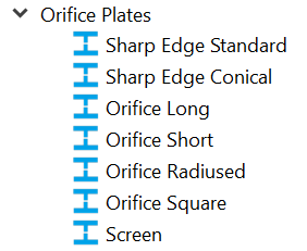
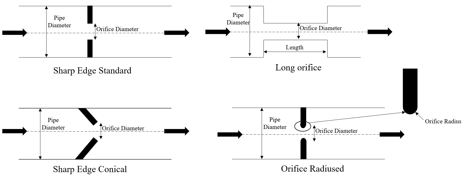
Orifice Element in Flow Simulator models the pressure loss across orifice plates using Loss characteristic curves obtained from Internal Flow Systems by DS Miller. Orifice Plates have a total of 7 sub-categories like Sharp Edge, Sharp Edge Conical, Orifice Long, Orifice Short, Orifice Radiused, Orifice Square and Screens. The mass flow rate calculations remain same for most of the cases. All the orifice plates elements can be used in Compressible (e.g. gas systems) and Incompressible (e.g. hydraulic and non-hydraulic systems)
Orifice diameter (area) and Pipe diameter (area) are mandatory inputs. Users can choose forward and reverse contraction coefficient from the drop down (By Default Miller curves are chosen). User can provide their own fixed or curve values for Contraction coefficient.
Orifice Plates Inputs
| Element Specific Conventional Orifice Element Input Variables | ||
| Index | Field | Description |
| 1 | Orifice Cross-Section Shape (CS_SHAPE) |
The cross-section inputs are available. 1: Circular with Area Specified (used for SUBTYPE=1-5) 2: Circular with Diameter Specified (used for SUBTYPE=1-5) 3: Square with Area Specified (used for Square Orifice) 4: Screen with Free Unobstructed Area Specified (used for Screen Orifice) |
| 2 | Orifice Area (ORIF_AREA) | Orifice mechanical area. Used with CS_SHAPE=1,3,4 |
| 3 | Pipe Area (PIPE_AREA) | Cross-section area of the pipe that feeds the orifice. Used with CS_SHAPE=1,3,4 |
| 4 | Orifice Diameter (ORIF_DIA) | Orifice diameter area. Used with CS_SHAPE=2 |
| 5 | Pipe Diameter (PIPE_DIA) | Diameter of the pipe that feeds the orifice. Used with CS_SHAPE=2 |
| 6 | Orifice Length (ORIF_LEN) | Orifice Length. Used for SUBTYPE=Long Orifice. |
| 7 | Orifice Edge Radius (ORIF_FRAD) | Fillet Radius of the orifice edge. Used with Long, Short, and Radiused Orifices. |
| 8 | Forward Contraction Coefficient (CC_FWD) |
The coefficient which is applied to the orifice geometry to determine the loss coefficient, K, for forward flow. Contraction Coefficient options are as follows: 1: 90-degree Flat Plate from D.S. Miller’s Internal Flow Systems 2nd Ed. Fig. 14.2. 2: 45 degree Conical from D.S. Miller’s Internal Flow Systems 2nd Ed. Fig. 14.2. Used for SUBTYPE=1 and 2. |
| 9 | Reversed Contraction Coefficient (CC_REV) |
The coefficient which is applied to the orifice geometry to determine the loss coefficient, K, for reverse flow. Contraction Coefficient options are as follows: 1: 90-degree Flat Plate from D.S. Miller’s Internal Flow Systems 2nd Ed. Fig. 14.2. 2: 45 degree Conical from D.S. Miller’s Internal Flow Systems 2nd Ed. Fig. 14.2. Used for SUBTYPE=1 and 2. |
| 10 | Element Multiplicity factor |
A single orifice element can have multiple streams within. Number of Streams Entering: Also referred as NLU Number of Streams Leaving: Also referred as NED |
| 11 | Element Inlet Orientation: Tangential Angle (THETA) |
Angle between the element centerline at the entrance of the element and the reference direction. If the element is rotating or directly connected to one or more rotating elements, the reference direction is defined as parallel to the engine centerline and the angle is the projected angle in the tangential direction. Otherwise, the reference direction is arbitrary but assumed to be the same as the reference direction for all other elements attached to the upstream chamber.
THETA for an element downstream of a plenum chamber has no impact on the solution except to set the default value of THETA_EX. (See also THETA_EX) |
| 12 | Element Inlet Orientation: Radial Angle (PHI) |
Angle between the element centerline at the entrance of the element and the THETA direction. (spherical coordinate system)
PHI for an element downstream of a plenum chamber has no impact on the solution except to set the default value of PHI_EX. (See also PHI_EX) |
| 13 | Element Exit Orientation: Tangential Angle (THETA_EX) |
Angle between the orifice exit centerline and the reference direction. THETA_EX is an optional variable to be used if the orientation of the element exit differs from that of the element inlet.
The default value (THETA_EX = -999) will result in the assumption that THETA_EX = THETA.
Other values will be interpreted in the manner presented in the description of THETA. |
| 14 | Element Exit Orientation: Radial Angle (PHI_EX) |
Angle between the orifice exit centerline and the THETA_EX direction.
PHI_EX is an optional variable to be used if the orientation of the element exit differs from that of the element inlet.
The default (PHI_EX = -999) will result in the assumption that PHI_EX = PHI.
Other values will be interpreted in the manner presented in the description of PHI. |
| 15 | Heat Input (QIN) | The value entered for QIN depends on the HEAT_MODE
chosen. See Element Heat Addition for more information. |
| 16 | Portion of Ustrm Chamb. Dyn. Head Lost (DQ_IN) | Inlet dynamic head loss. Refer General solver theory sections for more details about this input |
| 17 | K-Loss for Forward Flow (K_FWD) | User-defined K-loss coefficient. This input can be used with SUBTYPES=3-7. |
| 18 | K-Loss if flow reverses (K_REV) | User-defined K-loss coefficient in case flow reverses through the flow element. This input can be used with SUBTYPES=3-7. |
| 19 |
Reynolds Number Correction Relation for K (RE_CORR) |
The user can choose which to adjust K (or Cp) based according to the following options. 0: Off 1: Using Miller’s Internal Flow Systems 1st Ed. Fig. 14.33 or 2nd Ed. Fig. 14.32. |
| 20 | Edge Radius Correction Curve (RAD_CORR) |
Contraction Coefficient options are as follows: 0: No edge radius correction (used for SUBTYPE=1,2,6,7) 1: Edge radius correction from D.S. Miller’s Internal Flow Systems 2nd Ed. Fig. 14.4. Optional in SUBTYPE=5. |
| 21 | Rotor Index (RPMSEL) |
Reference rotor index for user-supplied swirl. Stationary (Database Value = 0.0) Rotor 1 (Database Value = 1.0): Points to general data Shaft 1 Rotor Speed. Rotor 2 (Database Value = 2.0): Points to general data Shaft 2 Rotor Speed Rotor 3 (Database Value = 3.0): Points to general data Shaft 3 Rotor Speed Rotates with Air (database Value = -1.0): Element RPM is based on upstream fluid RPM |
| 22 | Radius (RAD) |
Radius (in). Radial distance between the orifice inlet center and the engine centerline. (Do not use zero unless the orifice is not rotating) |
| 23 | Flow Equation Type (INCOMPR_FLG) |
Flag to specify flow compressibility for element calculations (Compressible vs. Incompressible). 1.0: Standard Compressible Flow 2.0: Incompressible gas 3.0: Incompressible Liquid |
| 24 | Compressibility Correction Curve (COMPR_CORR) |
Currently, the Flow Simulator GUI automatically sets this input according to FLUID_MODE. There are two options: 1: No Compressibility Correction in use (used if FLUID_MODE=2,3) 2: Curve from D.S. Miller Inertial Flow Systems 2nd Ed. Fig. 7.14 (used if FLUID_MODE=1. Later there may be more options.) |
Orifice Plates Element Theory
K loss values for various Orifice Plate Configurations
| Subtype | Curve Reference |
| Orifice: Sharp-Edged |
Forward Contraction Coefficient 90o (Miller, 2nd Ed., Fig 14.2) Reverse Contraction Coefficient 90o (Miller, 2nd Ed., Fig 14.2) |
| Orifice: Sharp-Edged Conical |
Forward Contraction Coefficient 45o (Miller, 2nd Ed., Fig 14.2) Reverse Contraction Coefficient 45o (Miller, 2nd Ed., Fig 14.2) |
| Orifice: Long |
Loss Coefficient for Thin Edged Sharp Orifice & Square Holes (Miller, 2nd Ed., Fig 14.3) Correction Factor for Edged Radii (Miller, 2nd Ed., Fig 14.4) Correction Factor for orifice length (Miller, 1st Ed., Fig 14.5) |
| Orifice: Short | Loss Coefficient for Thin Edged Sharp Orifice & Square Holes (Miller, 2nd Ed., Fig 14.3) |
| Orifice: Radiused |
Loss Coefficient for Thin Edged Sharp Orifice & Square Holes (Miller, 2nd Ed., Fig 14.3) Correction Factor for Edged Radii (Miller, 2nd Ed., Fig 14.4) |
| Orifice: Square | Loss Coefficient for Thin Edged Sharp Orifice & Square Holes (Miller, 2nd Ed., Fig 14.3) |
| Screens | Loss Coefficient for Screens (Miller, 2nd Ed.,
Fig 14.7) K for Grill at Inlet (Woods, reference 4) K for Grill at Outlet (Woods, reference 4) |
Apart from K Loss reference from “Internal Flow Systems” by DS Miller, Flow Simulator provides additional K Loss option from “Applied Fluid Dynamics, RD Blevins” (For Orifice Short Subtype) & I. E. Idelʹchik, Handbook of Hydraulic Resistance (For Orifice Long Subtype)
K Loss Calculation from IdelCheck for Long Orifice

Where
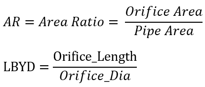
FRIC=Friction factor (Refer Solver General theory for Friction calculation)
PARAM1 = 1.0
PARAM2 = 1.5
PARAM3 = 2.0
IF (LBYD <= 0.2D0) THEN
TAU = 1.35D0 - 0.65D0 * LBYD
ELSEIF (LBYD <= 0.4D0) THEN
TAU = 1.34D0 - 0.60D0 * LBYD
ELSEIF (LBYD <= 0.6D0) THEN
TAU = 1.62D0 - 1.30D0 * LBYD
ELSEIF (LBYD <= 0.8D0) THEN
TAU = 2.10D0 - 2.10D0 * LBYD
ELSEIF (LBYD <= 1.0D0) THEN
TAU = 1.14D0 - 0.90D0 * LBYD
ELSEIF (LBYD <= 1.4D0) THEN
TAU = 0.59D0 - 0.35D0 * LBYD
ELSEIF (LBYD <= 2.0D0) THEN
TAU = 0.286666667D0 - 0.133333333D0 * LBYD
ELSEIF (LBYD <= 3.0D0) THEN
TAU = 0.06D0 - 0.02D0 * LBYD
ELSE
TAU = 0.0D0
ENDIF
K Loss Calculation from RD Blevins for Short Orifice
K Loss for Grills (Woods)

Mass Flow rate Calculation:
| Nomenclature: | |
| W: Mass flow rate | |
| A: Orifice mechanical area | R: Gas Constant |
| CD: Coefficient of Discharge | Ts: Static Temperature |
| K: Incompressible Loss Coefficient | |
| Tt: Total Temperature | MN: Vena Contracta Mach Number |
| Pt: Total pressure | Cp: Specific Heat |
| Ps: Static pressure | gc: Gravitational Constant |
| Subscripts: | |
| in: Inlet station | Corr: Correction |
| ex: exit station |
Incompressible Liquid Calculation:
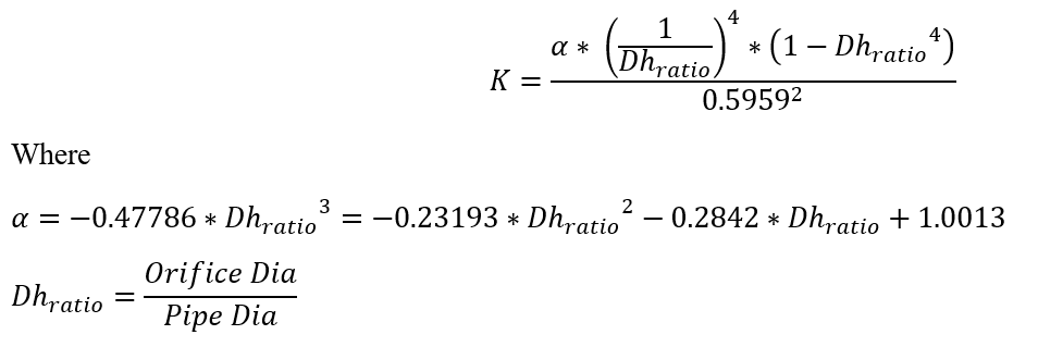
The Incompressible total loss coefficient is given by
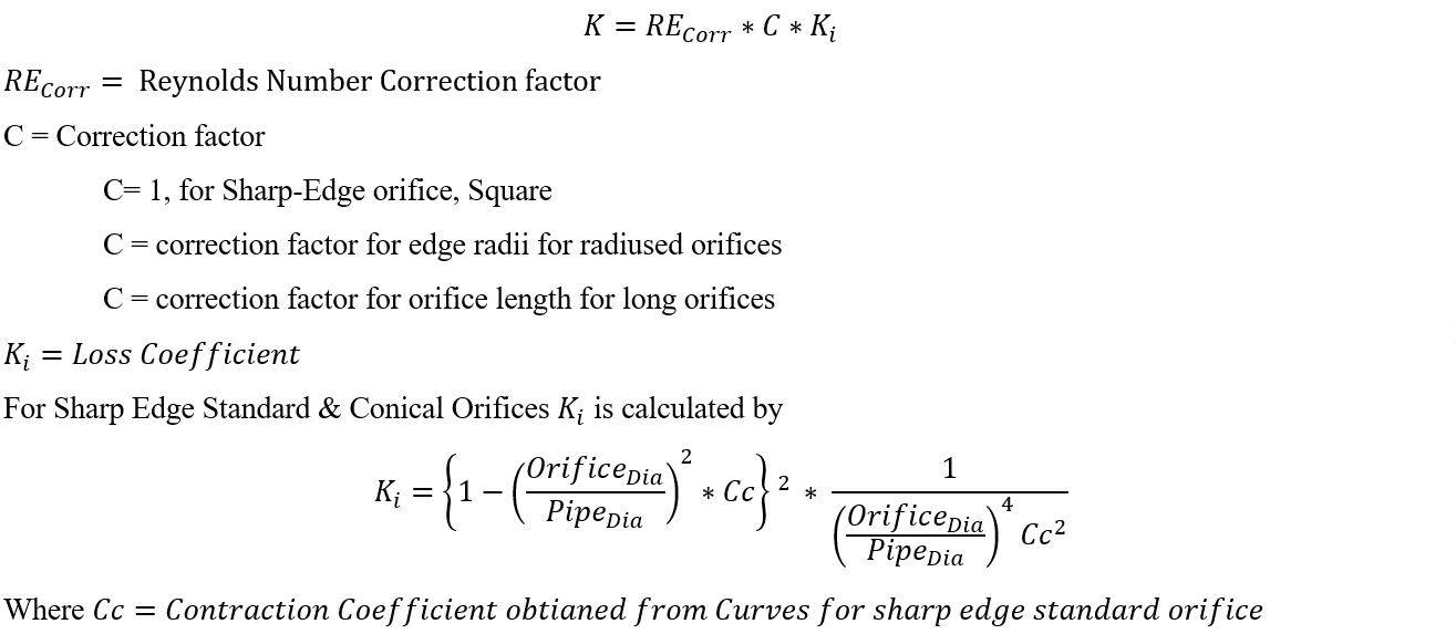
For all other subtypes, it is obtained directly from curve referenced above.
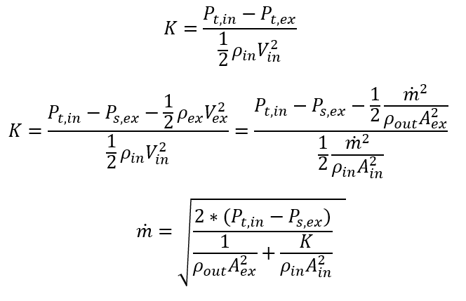
Mass flow rate across the element is calculated as follows
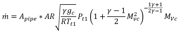
Compressible Gas Calculation:
Compressible Loss Coefficient, K is derived from incompressible loss coefficient, Ki with Compressibility correction factor. To obtain Compressibility correction coefficient, it is required to calculate the Mach number at Vena Contracta.
An iterative procedure is used to calculate mass flow rate & Mach Number at Vena contracta. The Compressibility Correction Coefficient is estimated using Curve (Fig 7.14 2 Ed., D.S. Miller)
Additional Momentum Loss
For Additional Momentum loss, Reynolds Number correction, Portion of Upstream Dynamic Head loss, Exit K Loss refer Solver General theory section.
Note: Reynolds Number is calculated based on orifice diameter & orifice Velocity
Orifice Plates Outputs
The following listing provides details about conventional orifice output variables. A graphical depiction of a conventional orifice output entry is provided.
| Name | Description | Units |
|---|---|---|
| Pipe Area | Usually an echo of the user input unless modified inside Flow Simulator. | in2, m2 |
| Orifice Area | Usually an echo of the user input unless modified inside Flow Simulator. | in2, m2 |
| Pipe Diameter | Usually an echo of the user input unless modified inside Flow Simulator. | in, m |
| Pipe Diameter | Usually an echo of the user input unless modified inside Flow Simulator. | in, m |
| DQ_IN |
Portion of Ustrm Chamb. Dyn. Head Lost (Usually an echo of the user input unless modified inside Flow Simulator.) |
flag |
| ELEMENT_THETA |
Tangential Angle (Usually an echo of the user input unless modified inside Flow Simulator.) |
unitless |
| ELEMENT_PHI |
Radial Angle (Usually an echo of the user input unless modified inside Flow Simulator.) |
unitless |
| REL_INLET_ANGLE | (Usually an echo of the user input unless modified inside Flow Simulator.) | deg |
| Orif_frad |
Orifice Fillet Radius (Orifice Edge Radius) (Usually an echo of the user input unless modified inside Flow Simulator.) |
in, m |
| Orif_Length |
Orifice length (Usually an echo of the user input unless modified inside Flow Simulator.) |
in, m |
| K_from Table_or_Eqn | Loss Value (Can be a User Input or Calculated by Flow Simulator) | |
| K_BeforeFilletCorrection | Uncorrected Loss Value (Calculated) | |
| FilletCorrection | Calculated Fillet Correction | |
| K_AfterFilletCorrection | Corrected Loss Value (User Input or Calculated) | |
| K_Loss_Input | Input Loss Value (Calculated) – If Constant Value is Provided | |
| K_Loss_Incompr | Loss Value (Calculated) | |
| K_Loss_Compr | Loss Value (Calculated) | |
| ELEMENT_RPM |
RPM (Rotor index) (Usually an echo of the user input unless modified inside Flow Simulator.) |
rad/min |
| RAD |
Radius (Usually an echo of the user input unless modified inside Flow Simulator.) |
in, m |
| Element Theta Exit | Exit Tangential Angle | rad |
| Element Phi Exit | Exit Radial Angle | rad |
| PTS | Driving pressure relative to the rotational reference frame (i.e. rotor) at the restriction inlet. | psi, mPa |
| PSIN | Static Pressure inlet. | psi, mPa |
| PTEX | Total pressure relative to the rotational reference frame (i.e. rotor) at the restriction exit including supersonic effects. | psi, mPa |
| PSEX |
Static pressure relative to the rotational reference frame (i.e. rotor) at the restriction exit. Limited by critical pressure ratio for supersonic flows. |
psi, mPa |
| PSEB | Effective sink (static) pressure downstream of the restriction. | psi, mPa |
| TTS | Total temperature of fluid relative to the rotational reference frame (i.e. rotor) at the restriction inlet. | deg F, K |
| TSIN | Static Temperature Inlet | deg F, K |
| TTEX | Total Temperature Exit | deg F, K |
| TSEX | Static Temperature Exit | deg F, K |
| QIN | Fraction of total heat to be added before the restriction. (0
= None, 1 = All) See Element Heat Addition for more information. |
BTU/s, W |
| INVEL | Inlet Velocity | ft/s, m/s |
| INMN | Inlet Mach Number | |
| INREYN | Inlet Reynolds Number | |
| EXVEL | Exit Velocity | ft/s, m/s |
| EXMN | Exit Mach Number | |
| EXREYN | Exit Reynolds Number | |
| PTVC | Total Pressure at Vena Contracta | psi, mPa |
| PSVC | Static Pressure at Vena Contracta | psi, mPa |
| TTVC | Total Temperature at Vena Contracta | deg F, K |
| TSVC | Static temperature at Vena Contracta | deg F, K |
| VCVEL | Velocity at Vena Contracta | ft/s, m/s |
| VCMN | Mach Number at Vena Contracta | ft/s, m/s |
| VEX | Fluid velocity relative to the rotational reference frame (i.e. rotor) at the restriction exit including heat input (QIN) effects. | ft/s, m/s |
| VABS | Magnitude of the fluid total absolute velocity | ft/s, m/s |
| VTAN_ABS | Magnitude of the fluid absolute tangential velocity | ft/s, m/s |
| VAXIAL | Magnitude of the fluid axial velocity | ft/s, m/s |
| VRAD | Magnitude of the fluid radial velocity | ft/s, m/s |
| THTA_ABS | Fluid absolute tangential flow angle | rad |
| VREL | Magnitude of the fluid total velocity relative to the element | ft/s, m/s |
| VTAN_REF | Reference frame tangential velocity | ft/s, m/s |
| VTAN_REL | Magnitude of the fluid tangential velocity relative to the element | ft/s, m/s |
| VNORM | Magnitude of the fluid total velocity relative to the element | ft/s, m/s |
| THTA_REL | Fluid relative tangential flow angle | rad |
| TTABS | Absolute total temperature | deg F, K |
| TTREL | Relative total temperature | deg F, K |
References
- Blevins, R. D., Applied Fluid Dynamics Handbook, Krieger Publications, 2003
- Miller, D, Internal Flow Systems, Miller Innovations, 1990
- I. E. Idelʹchik, Handbook of Hydraulic Resistance, CRC-Press, 1994
- Woods Practical Guide to Fan Engineering, Woods Colchester Ltd., Colchester, U.K., Jun. 1960