Diffuser Element
Diffuser General Description
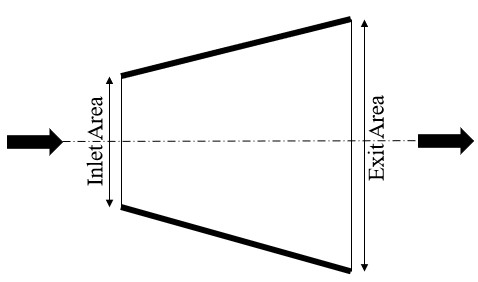
The FlowSimulator Diffuser element models the static pressure recoveries and total pressure losses across the diffusing passage for the given diffuser geometry & coefficient of Pressure. Diffuser is one key component of the gas turbine combustor following the compressor. Its primary function is to slow down the air flow delivered by the compressor in order to promote efficient combustion and avoid large total pressure losses.
Quick Guide for Diffuser Element Creation in the GUI
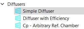
There are different subtypes of Diffuser elements available in FlowSimulator. All the diffuser elements can be used only in Compressible (e.g. gas systems) analysis. The various subtypes are
Diffuser Element Inputs
| Element Specific Diffuser Element Input Variables | ||
|---|---|---|
| Index | UI Name (. flo label) | Description |
| 1 | Diffuser Type (SUB_TYPE) |
The element subtype controls the diffuser type. 1.0: Simple Diffuser, input Cp, upstream chamber ref. pressure 2.0: Simple Diffuser, input effectiveness, upstream chamber ref. pressure 7.0: General Cp, input Cp, general chamber reference pressure |
Simple Diffuser with Cp (Subtype 1) Input Variables:
The following list the diffuser element inputs that are specific to the simple diffuser with an input Cp (subtype 1).
| Simple Diffuser with Cp (Subtype 1) Input Variables | ||
|---|---|---|
| Index | UI Name (. flo label) | Description |
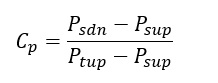
| 2 | CP (CP) |
Static Pressure Recovery Coefficient (Cp). It is only used if FL_TBL_TYP is 0 (indicating a constant Cp is to be used).
|
| 3 | Inlet Area (IN_AREA) | Diffuser inlet area |
| 4 | Exit Area (EX_AREA) |
Diffuser exit area By definition EX_AREA should be greater than IN_AREA. |
| 5 | Element Inlet Orientation: Tangential Angle (THETA) |
Angle between the element centerline at the entrance of the element and the reference direction. If the element is rotating or directly connected to one or more rotating elements, the reference direction is defined as parallel to the engine centerline and the angle is the projected angle in the tangential direction. Otherwise, the reference direction is arbitrary but assumed to be the same as the reference direction for all other elements attached to the upstream chamber.
THETA for an element downstream of a plenum chamber has no impact on the solution except to set the default value of THETA_EX. (See also THETA_EX) |
| 6 | Element Inlet Orientation: Radial Angle (PHI) |
Angle between the element centerline at the entrance of the element and the THETA direction. (spherical coordinate system)
PHI for an element downstream of a plenum chamber has no impact on the solution except to set the default value of PHI_EX. (See also PHI_EX) |
| 7 | Element Exit Orientation: Tangential Angle (THETA_EX) |
Angle between the orifice exit centerline and the reference direction. THETA_EX is an optional variable to be used if the orientation of the element exit differs from that of the element inlet.
The default value (THETA_EX = -999) will result in the assumption that THETA_EX = THETA.
Other values will be interpreted in the manner presented in the description of THETA. |
| 8 | Element Exit Orientation: Radial Angle (PHI_EX) |
Angle between the orifice exit centerline and the THETA_EX direction.
PHI_EX is an optional variable to be used if the orientation of the element exit differs from that of the element inlet.
The default (PHI_EX = -999) will result in the assumption that PHI_EX = PHI.
Other values will be interpreted in the manner presented in the description of PHI. |
| 9 | Inlet Loss (INLET_LOSS) | Inlet K or CD Value. Definition depends on value of the INLET_TYPE flag. INLET_LOSS = inlet K loss
Diffuser flow will be based on Cd * IN_AREA |
| 10 | Inlet Type (INLET_TYPE) | Flag for the type of inlet loss to apply to the diffuser. This FLAG controls the interpretation of the INLET_LOSS variable. |
| 11 | Exit Cd (CD_EX) |
Discharge Coefficient Element exit velocity and total pressure will be based on Cd * EX_AREA |
| 12 | Heat Input (QIN) |
Heat input. QIN is heat added to (positive values) or removed from (negative) the fluid flowing through the orifice.
In cases where multiple flow streams are modelled by a single element (i.e. NED and NLU not equal to 1), the value of QIN should be set to model the heat flow from only one of the restrictions. |
| 13 | Portion of Ustrm Chamb. Dyn. Head Lost (DQ_IN) | Inlet dynamic head loss. Refer General solver theory sections for more details about this input |
| 14 | Pressure Coef (FL_TBL_TYP) |
Flag that indicates the type of data in the FLOW_TBL array. 0 = Use the constant Cp 1 = FLOW_TBL array contains Mass Flow Rate 2 = FLOW_TBL array contains fractions of WRef (cycle flow in general data) 3 = FLOW_TBL array contains fractions of reference element’s flow (requires FLTB_RF_EL to be entered) |
| 15 | Reference Element for CP vs. Flow Fraction (FLTB_RF_EL) |
An element number that is used as the reference for a Cp vs “flow” table. Required to be nonzero only if FL_TBL_TYP = 3 |
| 16 |
Target Flow Or W2 Flow Frac Or Ref Elm Flow Frac (TGT_FLOW) |
Flow in lbm/sec or Flow Fraction used for the first iteration only. The interpretation of this field depends on the selection of FLOW_FLG, described below. Convergence does not seem to be very sensitive to this value especially when a fixed Cp is used. |
| 17 | Flow Guess Flag (FLOW_FLG) |
Flag that indicates the type of data in TGT_FLOW. 0 = Do not use TGT_FLOW 1 = TGT_FLOW contains mass flow rate 2 = TGT_FLOW contains a fraction of WRef (cycle flow in general data) 3 = TGT_FLOW contains a fraction of the reference element’s flow (requires REF_ELM to be entered) |
| 18 | Elem for Target Flow Fract (REF_ELM) | Reference Element for Target Flow Fraction or Reference Element for Inlet Area guessing. |
| 53 | CP vs Flow Table: Flow (FLOW_TBL) | Array of up to 20 “flows” for a Cp vs. Flow table. The units of the values in FLOW_TBL depend on the flag FL_TBL_TYP. |
| 54 | CP vs Flow Table: CP (CP_TBL) |
Array of up to 20 Cp values for a Cp vs. Flow table.
|
Simple Diffuser with Effectiveness (Subtype 2) Input Variables:
The following list the diffuser element inputs that are specific to the simple diffuser with an input effectiveness (subtype 2).
| Simple Diffuser with Effectiveness (subtype 2) Input Variables | ||
|---|---|---|
| Index | UI Name (. flo label) | Description |
| 2 | Effectiveness (CP) | Static Pressure Recovery Effectiveness. It’s only used if FL_TBL_TYP is 0 (indicating a constant effectiveness is to be used). |
| The rest of the inputs for this subtype are the same as subtype 1, simple diffuser with Cp except that effectiveness values are contained in the “CP_TBL” array instead of Cp values. | ||
General Cp (Subtype 7) Input Variables:
The following list the diffuser element inputs that are specific to the General Cp element. This element does not require an inlet area. This element can use a reference pressure for the CP from any chamber in the network.
| General Cp (Subtype 7) Input Variables | ||
|---|---|---|
| Index | UI Name (. flo label) | Description |
| 2 | Pressure Coefficient (CP) |
Static Pressure Recovery Coefficient (Cp). It’s only used if FL_TBL_TYP is 0 (indicating a constant Cp is to be used). The reference Ptotal and Pstatic are taken from chamber, REF_CH
|
| 4 | Exit Area (EX_AREA) | Diffuser exit area |
| 5 | Element Inlet Orientation: Tangential Angle (THETA) |
Angle between the element centerline at the entrance of the element and the reference direction. If the element is rotating or directly connected to one or more rotating elements, the reference direction is defined as parallel to the engine centerline and the angle is the projected angle in the tangential direction. Otherwise, the reference direction is arbitrary but assumed to be the same as the reference direction for all other elements attached to the upstream chamber.
THETA for an element downstream of a plenum chamber has no impact on the solution except to set the default value of THETA_EX. (See also THETA_EX) |
| 6 | Element Inlet Orientation: Radial Angle (PHI) |
Angle between the element centerline at the entrance of the element and the THETA direction. (spherical coordinate system)
PHI for an element downstream of a plenum chamber has no impact on the solution except to set the default value of PHI_EX. (See also PHI_EX) |
| 7 | Element Exit Orientation: Tangential Angle (THETA_EX) |
Angle between the orifice exit centerline and the reference direction. THETA_EX is an optional variable to be used if the orientation of the element exit differs from that of the element inlet.
The default value (THETA_EX = -999) will result in the assumption that THETA_EX = THETA.
Other values will be interpreted in the manner presented in the description of THETA. |
| 8 | Element Exit Orientation: Radial Angle (PHI_EX) |
Angle between the orifice exit centerline and the THETA_EX direction.
PHI_EX is an optional variable to be used if the orientation of the element exit differs from that of the element inlet.
The default (PHI_EX = -999) will result in the assumption that PHI_EX = PHI.
Other values will be interpreted in the manner presented in the description of PHI. |
| 12 | Heat Input (QIN) |
Heat input. QIN is heat added to (positive values) or removed from (negative) the fluid flowing through the orifice.
In cases where multiple flow streams are modelled by a single element (i.e. NED and NLU not equal to 1), the value of QIN should be set to model the heat flow from only one of the restrictions. |
| 14 | Pressure Coef (FL_TBL_TYP) |
Flag that indicates the type of data in the FLOW_TBL array. 0 = Do not use the Cp vs. flow tables, use the constant Cp 1 = FLOW_TBL array contains mass flow rate 2 = FLOW_TBL array contains fractions of WRef (cycle flow in general data) 3 = FLOW_TBL array contains fractions of reference element’s flow (requires FLTB_RF_EL to be entered) |
| 15 | Elem for Cp vs. Flow Fract (FLTB_RF_EL) |
An element number that is used as the reference for a Cp vs “flow” table. Required to be nonzero only if FL_TBL_TYP = 3 |
| 16 |
Target Flow Or W2 Flow Frac Or Ref Elm Flow Frac (TGT_FLOW) |
Flow in lbm/sec or Flow Fraction used for the first and second iteration only. The interpretation of this field depends on the selection of FLOW_FLG, described below. This type of element is fairly sensitive to the initial guess. An estimate within 20% of the final flow is recommended, if it is known. |
| 17 | Flow Guess Flag (FLOW_FLG) |
Flag that indicates the type of data in TGT_FLOW. 0 = Do not use TGT_FLOW 1 = TGT_FLOW contains flow in lbm/sec 2 = TGT_FLOW contains a fraction of WRef (cycle flow in general data) 3 = TGT_FLOW contains a fraction of reference element’s flow (requires REF_ELM to be entered) |
| 18 | Elem for Target Flow Fract (REF_ELM) |
Reference Element for Target Flow Fraction When FLOW_FLG = 3, this field is intended for storing the element number that contains the flow that is being referenced for a flow fraction. |
| 19 | Chamber for Pressure Recovery (REF_CH) | Chamber used for the reference total and static pressures in the Cp calculation. |
| 53 | Flow Table (FLOW_TBL) | Array of up to 20 “flows” for a Cp vs. Flow table. The values in FLOW_TBL depend on the flag FL_TBL_TYP. |
| 54 | CP Table (CP_TBL) |
Array of up to 20 Cp values for a Cp vs. Flow table.
|
Diffuser Theory Manual
Calculation of Flow Rate
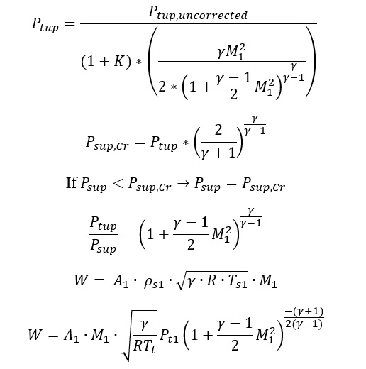
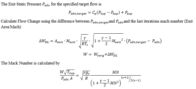
For Subtypes (1,2) the Mass flow rate through the diffuser is obtained as derived below,
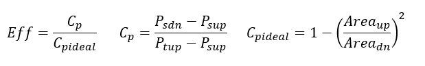
If Effectiveness is provided (Subtype=2)
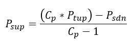
Static Pressure Upstream is calculated from as follows
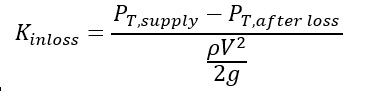
The Upstream Total Pressure ( is corrected for inlet K Loss
Diffuser Element Outputs
The following listing provides details about the Simple CP diffuser output variables
| Name | Description | Units |
|---|---|---|
| PT1 | Total pressure at the inlet of the diffuser. | psi, mPa |
| PS1 | Static pressure at the inlet of the diffuser. | psi, mPa |
| TTS | Total temperature at the inlet of the diffuser. | deg F, K |
| MN1 | Fluid Mach number at the inlet of the diffuser. | (unitless) |
| IN_AREA | Inlet area of the diffuser. | inch2, m2 |
| CDIN/KIN |
Inlet discharge coefficient or head loss coefficient of the diffuser, depending on which inlet loss type was chosen. (Echo of the user input.) |
(fraction) |
| PT2 | Total pressure at the exit of the diffuser. | psi, mPa |
| PS2 | Static pressure at the exit of the diffuser. | psi, mPa |
| TEX | Total temperature at the exit of the diffuser. | deg F, K |
| MN2 | Fluid Mach number at the exit of the diffuser. | (unitless) |
| EX_AREA | Exit area of the diffuser. | inch2, m2 |
| CDEX |
Exit discharge coefficient of the diffuser. (Echo of the user input.) |
(fraction) |
| PTLS% | Percent of total pressure loss across the diffuser. | % |
| CPACT | Actual pressure coefficient (CP) across the diffuser that was calculated (or defined). | (unitless) |
| CPIDL | Ideal CP based on the geometry (area ratio) of the diffuser. | (unitless) |
| EFF | Diffuser effectiveness (CP / Ideal CP). | (fraction) |
| ARATIO | Area ratio from inlet to exit of the diffuser. | (unitless) |
The following listing provides details about the General CP diffuser output variables
| Name | Description | Units |
|---|---|---|
| PT0 | Total pressure at the reference chamber. | psi, mPa |
| PS0 | Static pressure at the reference chamber. | psi, mPa |
| REF_CH | Reference chamber used for the pressure recovery calculation. | (N/A) |
| PT2 | Total pressure at the exit of the element. | psi, mPa |
| PS2 | Static pressure at the exit of the element. | psi, mPa |
| TEX | Total temperature at the exit of the element. | deg F, K |
| MN2 | Fluid Mach number at the exit of the element. | (unitless) |
| EX_AREA | Cross-Sectional area for exit condition calculations. | inch2, m2 |
| CDEX |
Exit discharge coefficient. (Echo of the user input.) |
(fraction) |
| CPACT | Actual pressure coefficient (CP) across the element (between the reference chamber and exit). | (unitless) |
| CPTRG | Target CP the element was attempting to reach by iteration. | (unitless) |