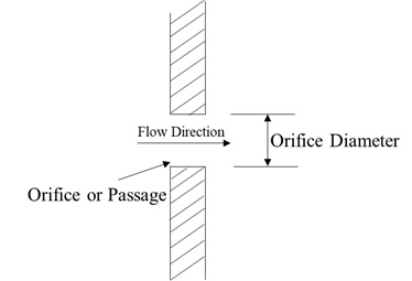
Orifice Element
Description
The orifice element models a pressure loss between two chambers within a system, where the only purpose of the element is to model a flow restriction with losses within the system (for example, a simple aperture, coolers, strainers, fittings, leakages, or sudden changes in cross section). The orifice may be fixed in space or rotating about the engine centerline, and each may be positioned at any angle relative to the coordinate system. Orifice elements use an input of orifice mechanical area/diameter and loss parameters with a standard isentropic flow relationship to calculate the element flow rates. The loss parameter can be the Coefficient of discharge (Cd) or the Incompressible Loss Coefficient (K). This element does not model any fluid inertia.
Create Orifice Elements in the GUI
In Flow Simulator, there are different orifice element subtypes. All orifice elements can be used in compressible (for example, gas systems) and incompressible (for example, hydraulic and non-hydraulic systems) analysis. The subtypes are described below.
Conventional Orifice

- Provide the nozzle efficiency to convert the conventional orifice to nozzle.
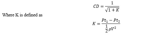
- Cd (discharge coefficient) for an orifice element can be a value between 0+ and 1.0 as input.
- Provide the Incompressible Loss coefficient (K) as input. Allowable Kloss
values are 0 to 10. The discharge coefficient is calculated by the
incompressible relationship:
Heater Cooler

Heater cooler is the same as the conventional orifice, but this specific subtype exists if you need to model flow restrictions with heat addition/removal across the restriction. The mandatory inputs are the same as for conventional orifice (area, loss coefficient) along with the heat addition mode and its required inputs.
You can apply the following heat modes:
- Heat addition: Specify heat input, (+) input model heat addition, and (-) input model heat removal.
- Heat addition per mass flow: Specify heat input per mass flow.
- Fluid delta Tt: Specify the delta total temperature rise across the orifice. (+) Input model heat addition and (-) input model heat removal.
- Fixed fluid Tt Exit: Specify the exit temperature of the orifice.
Discrete Loss
With the discreet loss subtype, specify the delta total pressure loss (Pt1-Pt2) across the restrictions directly to model restriction losses, in addition to the loss parameters option (Cd or K). Mandatory inputs cross sectional area or diameter and CD or K or Delta. P (Pt1-Pt2) value. Cd (discharge coefficient) for a discrete loss element is a value between 0+ and 1.0. There is no input restriction on the upper limit of Kloss values for the discrete loss element.
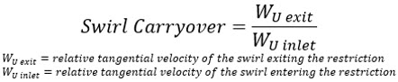
Swirl Carryover Orifice
The tangential velocity calculation for the swirl carryover orifice element is the only difference between it and the conventional orifice. The swirl carryover is a fraction of upstream tangential velocity that is carried over to the downstream.
Orifice Element Inputs
| Element-Specific Conventional Orifice Element Input Variables | ||
|---|---|---|
| Index | UI Name (.flo Label) | Description |
| 1 | Area (AREA) Diameter (DIA) |
Orifice mechanical area Orifice diameter |
| 2 |
Cd – Compressible Loss Coefficient Or K – Incompressible Loss Coefficient [Head Loss] Or CV - Flow Coefficient |
Cd or K Value For all Subtypes, 0 < CD ≤ 1 For the conventional orifice, 0 ≤ K ≤ 10 For Discrete Loss, K ≥ 0 Flow coeffiecient for the orifice. Units: USGPM/psi1/2 or m3/hr/bar1/2(metric equivalent of CV or KV) |
| 3 | Exit Area Cross Flow (EXIT_XFLOW) | Not used. |
| 4 | Element Inlet Orientation: Tangential Angle (THETA) | Angle between the element centerline at the entrance of the
element and the reference direction. If the element is rotating or directly connected to one or more rotating elements, the reference direction is defined as parallel to the engine centerline, and the angle is the projected angle in the tangential direction. Otherwise, the reference direction is arbitrary, but assumed to be the same as the reference direction for all other elements attached to the upstream chamber. THETA for an element downstream of a plenum chamber has no impact on the solution, except to set the default value of THETA_EX. See also THETA_EX. |
| 5 | Element Inlet Orientation: Radial Angle (PHI) | Angle between the element centerline at the entrance of the
element and the THETA direction (spherical coordinate system). PHI for an element downstream of a plenum chamber has no impact on the solution, except to set the default value of PHI_EX. See also PHI_EX. |
| 6 | Radius (RAD) | Radius. Radial distance between the orifice inlet center and the
engine centerline. Do not use zero unless the orifice is not rotating. |
| 7 | Heat Mode (HEAT_MODE) | Mode of heat transfer to/from the fluid in the element. See Element Heat Addition for more information. |
| 8 | Rotor Index (RPMSEL) | Reference rotor index for user-supplied swirl. Stationary
(database value = 0.0). Rotor 1 (database value = 1.0): Points to general data shaft 1 rotor speed. Rotor 2 (database value = 2.0): Points to general data shaft 2 rotor speed. Rotor 3 (database value = 3.0): Points to general data shaft 3 rotor speed. Rotates with air (database value = -1.0): Element RPM is based on upstream fluid RPM. |
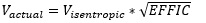
| 9 | Efficiency (EFFIC) | Nozzle efficiency. Entry of a number between 0.0 and 1.0 causes Flow Simulator to treat this orifice as a convergent-divergent nozzle with a nozzle efficiency of EFFIC. The flow calculation is identical to the standard orifice, but the exit velocity is calculated using the equation:
where Visentropic depends on the driving pressure ratio across the orifice. |
| 10 | Heat Input (QIN) | The value entered for QIN depends on the HEAT_MODE chosen. See Element Heat Addition for more information. |
| 11 | Portion of Ustrm Chamb. Dyn. Head Lost (DQ_IN) | Inlet dynamic head loss. Valid range is 0.0 to 1.0, inclusive. An
entry outside this range causes a warning message and the value used
will be 0 or 1 (whichever value is closest to the entry). If DQ_IN > 0, and the upstream chamber has a positive component of relative velocity aligned with the centerline of the orifice, the driving pressure is reduced by the equation: Default value = 0. |
|
12 13 14 |
Exit K Loss:
|
Head loss factors in the Z, U, and R directions, based on the
spherical coordinate system of theta and phi. Default value provides
no loss. Refer to the general solver theory sections for more details about this input. |
| 15 | Element Exit Orientation: Tangential Angle (THETA_EX) | Angle between the orifice exit centerline and the reference
direction. THETA_EX is an optional variable to be used if the orientation of the element exit differs from that of the element inlet. The default value (THETA_EX = -999) results in the assumption that THETA_EX = THETA. Other values are interpreted in the manner presented in the description of THETA. |
| 16 | Element Exit Orientation: Radial Angle (PHI_EX) | Angle between the orifice exit centerline and the THETA_EX
direction. PHI_EX is an optional variable to be used if the orientation of the element exit differs from that of the element inlet. The default (PHI_EX = -999) results in the assumption that PHI_EX = PHI. Other values are interpreted in the manner presented in the description of PHI. |
| 17 | QIN_RATIO | Fraction of total heat to be added before the restriction. (0 =
None, 1 = All) See Element Heat Addition for more information. |
| 18 | Flow Equation Type (INCOMPR_FLG) | Flag to specify flow compressibility for element calculations
(compressible versus incompressible). For incompressible flow options (1 or 2), fluid density can be calculated using either upstream or downstream static pressure. For combustor models, option 1 is usually used to model swirler cups, while option 2 is used to model cooling and dilution holes. 0.0: Standard compressible flow 3.0: Incompressible liquid |
| 19 | EXIT AREA (EXIT_AREA) | Orifice exit area calculates the exit conditions (to account for
additional pressure loss due to sudden change in the area). If the value is 0.0, exit conditions are only based on the orifice mechanical area and losses associated with the orifice. |
| 20 | Reverse Loss Coefficient (CD_REV) | Flag for calculating the discharge coefficient, Cd, or the loss
coefficient, K, when the orifice flow direction is
reversed. CD_REV=0, CD_REV is the same as CD (forward). |
| 21 | SUB_TYPE | The orifice element subtype, such as fixed pressure drop, discrete loss, CV element, and so on. |
| 22 | (LOSS_MODE) | |
| 23 | XT – Pressure differential ratio factor (XT) |
For CV Element only. Determines choking for flow of compressible
fluids. Range: > 0 to 1 |
| 24 | FL – Liquid Pressure recovery factor (FL) |
For CV Element only. Always needed for incompressible fluid. Only needed for compressible if laminar flow. Range: > 0 to 1 |
| 25 | FD – Valve Style Modifier (FD) |
For CV Element only. Used for laminar flow for both compressible and incompressible fluids. Ratio of hydraulic diameter of a flow passage to the hydraulic diameter of a circular orifice. Range: > 0 to 1 |
| Element Multiplicity factor (NLU and NED) |
A single orifice element can have multiple streams within.
Number of Streams Entering: Also referred to as NLU. Number of Streams Leaving: Also referred to as NED. |
|
| Swirl Carryover | Can be none or fixed swirl carryover. For fixed swirl carryover, you must input the value. |
|
Orifice Theory Manual
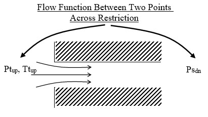
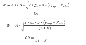
The isentropic flow function defines the flow through an orifice restriction in terms of upstream total pressure, upstream total temperature, downstream static pressure, and cross-sectional flow area. Since the flow function is derived with the assumption of isentropic flow, some sort of empirical correction is required to account for the irreversible losses encountered in the orifices. This is usually represented as a discharge coefficient or loss coefficient, included in the working definition of the flow function, and represents the ratio of actual (empirical) to ideal (isentropic) flow rates.
| Nomenclature | |
|---|---|
| W: Mass flow rate | Specific heat ratio |
| A: Orifice mechanical area | R: Gas constant |
| CD: Coefficient of discharge | Ts: Static temperature |
| K: Incompressible loss coefficient | Density |
| Tt: Total temperature | MN: Vena contracta mach number |
| Pt: Total pressure | Cp: Specific heat |
| Ps: Static pressure | gc: Gravitational constant |
| CV: Flow coefficient | |
| Subscripts | |
|---|---|
| up: Upstream station | |
| dn: Downstream station | |
| b: Back |
Flow Rate Calculation and Vena Contracta Mach Number - Conventional Orifice, Heater Cooler, and Discrete Loss
The element flow is calculated using the following equations:
Compressible flow:
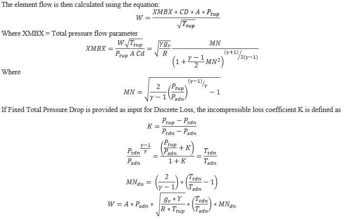
Incompressible flow equation:
Orifice Exit Conditions Calculation
The flow is first expanded from the vena contracta throat to the exit conditions before any effect of heat addition, QIN, is considered. It is assumed that the flow is expanded adiabatically (limited to Mach number = 1.0) to the mechanical area of the orifice at the exit static pressure. The static pressure exit flow parameter, exit Mach number, and adiabatic exit velocity are calculated as:
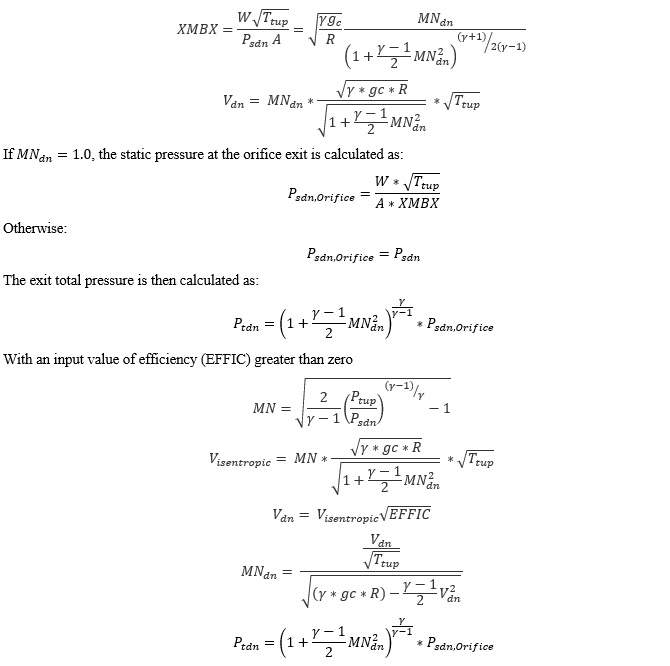
The effect of heat addition specified as QIN is added next, assuming that only the exit temperature and velocity, and not the exit Mach number, are affected. The temperature rise (or drop if QIN is negative) is calculated using an average value of specific heat (Cp).
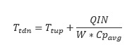
Cpavg: Specific heat at the average of TTS and TEX, pressure PSEX, and secondary fluid mass fraction FS(IC).
Next, a new exit velocity is calculated as:
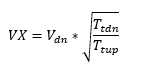
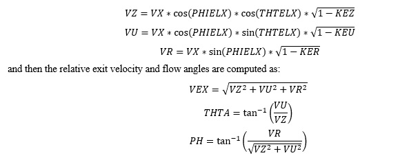
If 0 values are input for each of the exit head loss variables (KEZ, KEU, and KER), the element exit velocity, VEX, is set to VX, and the relative radial and tangential flow angles at the exit plane (THTA and PH) are taken to be the values specified for the input variables THTELX and PHIELX, respectively. If any of these exit head loss variables are input as non-zero values, the exit velocity components are recomputed as:
Swirl Carryover Orifice Element Tangential Velocity
For long holes (L/D > 1) the swirl carryover is low (often near 0). This means the swirl from upstream of the restriction does not affect the swirl exiting the restriction (the rotation of the hole itself is what determines the swirl exiting the restriction).
Additional Momentum Loss
For additional momentum loss, see Portion of Upstream Dynamic Head loss and Exit K Loss.
CV Element
In orifices, CV Element refers to the orifice type that is characterized by the flow coefficient or CV value. This element calculates the flow rate through an orifice whose CV value is specified, and the upstream and downstream pressures are known or calculated. CV is defined as the amount of flow passing through the orifice at standard temperature under a unit pressure drop between the upstream and downstream locations. For many orifices and valves, the CV value is specified by the manufacturer.
Incompressible Flow
- Non-choked turbulent flow through orifices:
- Choked turbulent flow through orifices:
Where, is the upstream static pressure and is the downstream static pressure. is the fluid density at upstream temperature, is the fluid density at 1 atm and 150 C. PV is the vapor pressure of fluid at upstream flow conditions. N1 is a numerical constant depending upon the unit set, for W in lbm/hr, CV in USGPM/psi1/2, densities in lbm/ft3, and pressure in psi, N1, is 8.0208.
Fp is called the piping geometry factor and accounts for the effects of attached fittings. For more information on FP, refer to Valve Elementst. For orifices, no attached fittings are considered, therefore, Fp = 1.
FLP is called the combined liquid pressure recovery and piping geometry factor with attached fittings. It accounts for the combined effects of attached fittings (FP) and liquid pressure recovery (FL) through the internal geometry of the orifices. However, for the orifices, since no attached fittings are considered, FLP = 1.
FL is called the liquid pressure recovery factor for the orifice, ranging from 0 to 1. It is user defined for the orifice CV element. It accounts for the effect of component internal geometry on the flow capacity. The liquid pressure recovery factor is defined as the ratio of the maximum flow rate through the component at choked flow conditions to a theoretical non-choked flow rate obtained between upstream pressure and apparent vena-contracta pressure at choked flow conditions [1]. Since FL is determined through testing, it is generally supplied by the manufacturer.
Check for choked flow conditions [1]:
The incompressible flow for the CV Element is choked if:
Where FF is the liquid critical pressure ratio factor. It is a ratio of vapor pressure of fluid at upstream flow conditions to thermodynamic critical pressure of the fluid, given by [1]:
Compressible Flow
- Non-choked turbulent flow through the orifice:
- Choked turbulent flow through the orifices:
Where, is the upstream static pressure and is the downstream static pressure. is a gas density at upstream temperature. N6 is a numerical constant depending upon the unitset, for W in lbm/hr, CV in USGPM/psi1/2, densities in lbm/ft3, and pressure in psi, N6, is 63.3.
Fp is called the piping geometry factor and accounts for the effects of attached fittings. For more information on FP, refer to Valve Elements. For orifices, no attached fittings are considered, therefore, Fp = 1.
Y is an expansion factor that accounts for changes in densities as the fluid passes through the orifice inlet to the region of vena contracta.
X is the ratio of pressure difference between the upstream and downstream to the total pressure upstream.
XT is the pressure differential ratio factor for the orifice, without any reducer or attached fittings, with values ranging from 0 to 1. It is user defined for the orifice CV element. The mass flow through the orifice reaches a limiting value when X reaches FγXT (choked flow conditions). Since XT is determined through air testing, it is generally supplied by the manufacturer.
Fγ is the specific heat ratio. It is the ratio of specific heat of the flowing fluid to the specific heat of air. If the specific heat of flowing fluid is different than air, Fγ is used to adjust XT.
Check for choked flow conditions [1]:
The compressible flow for the CV Element is choked if: X ≥ FγXT.
Non-Turbulent (Transitional and Laminar) Flow
A Reynolds number is calculated to determine if the flow is non-turbulent. The flow rate from the turbulent equations will be reduced for Reynolds numbers < 10,000.
- For full size trim and transitional flow regime:ref.1 eq. F.1a
- For full size trim and laminar flow regime:ref.1 eq. F.2
- For reduced trim and transitional flow regime:ref.1 eq. F.3a
- For reduced trim and laminar flow regime:ref.1 eq. F.4
The lowest FR is selected from the transitional and laminar equations. FR is limited to the range 0.02 and 1.0.
Orifice Element Outputs
The following table contains the conventional orifice output variables.
| Name | Description | Units |
|---|---|---|
| DQ_IN | Portion of Ustrm Chamb. Dyn. Head Lost Usually, an echo of the user input unless modified inside Flow Simulator. |
Flag |
| Axial (K_EXIT_Z) Tangential (K_EXIT_U) Radial (K_EXIT_R) |
Exit K loss Usually, an echo of the user input unless modified inside Flow Simulator. |
Unitless |
| ELEMENT_THETA | Tangential angle Usually, an echo of the user input but converted to radians. |
radians |
| ELEMENT_PHI | Radial angle Usually, an echo of the user input but converted to radians. |
radians |
| REL_INLET_ANGLE | A relative inlet angle, calculated based on the upstream chamber velocity. | deg |
| ELEMENT_RPM | RPM (rotor index) Usually, an echo of the user input unless modified inside Flow Simulator. |
rad/min |
| RAD | Radius Usually, an echo of the user input unless modified inside Flow Simulator. |
in, m |
| ELEMENT_AREA | Cross-sectional area Usually, an echo of the user input unless modified inside Flow Simulator. |
inch2, m2 |
| CD | Discharge coefficient Usually, an echo of the user input unless modified inside Flow Simulator. |
fraction |
| CV KV for SI |
Flow coefficient value for the orifice CV Element. Usually, an echo of the user input unless modified inside Flow Simulator. |
GPM/psi1/2 m3/hr/bar1/2 |
| XT | Compressible CV Element only. | (unitless) |
| FL | CV Element only Usually, an echo of the user input unless modified inside Flow Simulator. |
(unitless) |
| FD | CV Element only Usually, an echo of the user input unless modified inside Flow Simulator. |
(unitless) |
| FR | CV Element only Reynolds number Flow Factor Only less than 1 for non-turbulent flow. |
(unitless) |
| RE | CV Element only Reynolds Number, CV element non-turbulent if RE < 10,000 |
(unitless) |
| K | Head loss coefficient Calculated from the discharge coefficient using equation. |
(unitless) |
| K | Head loss coefficient Calculated from the discharge coefficient using an equation. |
unitless |
| EXIT_AREA | Exit area used for calculating exit conditions of the orifice
element. This output is only printed when an exit area is used
(EXIT_AREA>0). A default value of 0 has no effect on exit
conditions. Output is an echo of the user input. |
inch2, m2 |
| PTS | Driving pressure relative to the rotational reference frame (rotor) at the restriction inlet. | psi, mPa |
| PTEX | Total pressure relative to the rotational reference frame (rotor) at the restriction exit including supersonic effects. | psi, mPa |
| PSEX | Static pressure relative to the rotational reference frame
(rotor) at the restriction exit. Limited by critical pressure ratio for supersonic flows. |
psi, mPa |
| PSEB | Effective sink (static) pressure downstream of the restriction. | psi, mPa |
| TTS | Total temperature of fluid relative to the rotational reference frame (rotor) at the restriction inlet. | deg F, K |
| VCMN | Fluid Mach number relative to the rotational reference frame (rotor) at the vena contracta. | unitless |
| VXA | Fluid velocity relative to the rotational reference frame (rotor) at the restriction exit before heat input (QIN) effects. | ft/s, m/s |
| RHO | Density of fluid at upstream temperature and downstream sink
(static) pressure. For incompressible only. |
lbm/ft3 kg/m3 |
| GPM | Flow rate of fluid through the element in US GPM. For incompressible only. |
|
| EXMN | Fluid Mach number relative to the rotational reference frame (rotor) at the restriction exit before heat input (QIN) effects. | unitless |
| QIN | Heat input Positive values indicate heat added to the fluid; negative values indicate heat removed. |
BTU/s, W |
| DT | Change in total temperature relative to the rotational reference frame (rotor) due to heat input (QIN). | deg F, K |
| TEX | Total temperature relative to the rotational reference frame (rotor) at the restriction exit. | deg F, K |
| VEX | Fluid velocity relative to the rotational reference frame (rotor) at the restriction exit including heat input (QIN) effects. | ft/s, m/s |
| VABS | Magnitude of the fluid total absolute velocity. | ft/s, m/s |
| VTAN_ABS | Magnitude of the fluid absolute tangential velocity. | ft/s, m/s |
| VAXIAL | Magnitude of the fluid axial velocity. | ft/s, m/s |
| VRAD | Magnitude of the fluid radial velocity. | ft/s, m/s |
| THTA_ABS | Fluid absolute tangential flow angle. | rad |
| VREL | Magnitude of the fluid total velocity relative to the element. | ft/s, m/s |
| VTAN_REF | Reference frame tangential velocity. | ft/s, m/s |
| VTAN_REL | Magnitude of the fluid tangential velocity relative to the element. | ft/s, m/s |
| VNORM | Magnitude of the fluid total velocity relative to the element. | ft/s, m/s |
| THTA_REL | Fluid relative tangential flow angle. | rad |
| TTABS | Absolute total temperature. | deg F, K |
| TTREL | Relative total temperature. | deg F, K |
References
- ISA-75.01.01-2007, Flow Equations for Sizing Control Valves