Elements Overview
Flow Simulator Elements Overview
Each Flow Simulator element represents a flow path between one chamber and another. There are a number of standard element types that represent common restrictions such as tubes, orifices, valves, transitions etc., and more complex restrictions like junctions, seals, bearings etc. The Flow Simulator solution process involves passing through type-specific element subroutines in which, for given upstream and downstream chamber states, calculations are made of the element flow rate, element exit flow state and element flow derivatives with respect to up and downstream pressure. The vortex is a unique element type. Its purpose is to include the temperature, pressure, and swirl change associated with rotating flow. The vortex flow rate is not calculated based on upstream and downstream pressure but is calculated from a flow balance at the upstream and downstream chambers. The following sections will discuss the general calculations done for all element types as well as specific calculations unique to each different type.
Computing Element Inlet Conditions
The analysis method of the element inlet flow state is determined by the upstream chamber type. The variables required to define the inlet flow state are
PTS: Inlet total pressure
TTS: Inlet total relative temperature
FSS: Inlet secondary fluid mass fraction
WUU: Magnitude of fluid tangential velocity relative to the rotational reference frame (i.e. rotor) at the element inlet
WRU: Magnitude of fluid radial velocity at the element inlet
WZU: Magnitude of fluid axial velocity at the element inlet
In Addition to the above the three components of the crossflow velocity where crossflow is defined as the component of velocity perpendicular to the axis of the element
WCUU: Magnitude of fluid tangential velocity relative to the rotational reference frame (i.e. rotor) at the element inlet perpendicular to the element axis
WCRU: Magnitude of fluid radial velocity at the element inlet perpendicular to the element axis
WCZU: Magnitude of fluid axial velocity at the element inlet perpendicular to the element axis
If the element angle variables are both zero (i.e. the element axis is parallel to the engine centerline) the calculated crossflow components will be the same as the corresponding relative velocity component. When crossflow effects are included in the analysis of flow through an element, the use of simple relative velocity components or the above crossflow components relative to the element axis will depend on the way the data used in developing the analytical method was correlated.
Independent of upstream chamber type, the inlet secondary fluid mass fraction, FSS, is simply the secondary fluid mass fraction in the upstream chamber,
FSS=FS(IC)
Before calculations are begun, the properties subroutine is called to obtain fluid properties at the upstream chamber conditions (static pressure, total temperature, and secondary fluid mass fraction). The properties returned are specific heat ratio (XG), gas constant (XR), and specific heat at constant pressure (XCP).
Upstream Relative Velocity Calculation
The first step in the process to determine the element inlet conditions is to determine the relative velocity components. These are derived from the velocity components in the upstream chamber, the effects of element rotation about the engine centerline, and relative angles.
Upstream Plenum Chamber
If the upstream chamber is a plenum, the chamber is assumed to have no motion relative to the element . Since velocity is zero in a plenum, the relative velocity components in the tangential, axial and radial directions and the total relative velocity are:
WU=0.
WZ=0.
WR=0.
WTOT=0.
Upstream Momentum Chamber
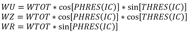
If there is a momentum chamber upstream, the chamber is assumed to have no motion relative to the element so the relative velocity at the element inlet is the same as the chamber velocity. The chamber Mach number, XMRES, is used to carry velocity so the resultant velocity is obtained using the Mach number routine and the chamber temperature TTC(IC):
![]()
The velocity components are computed using the equations,
Upstream Inertial Chamber
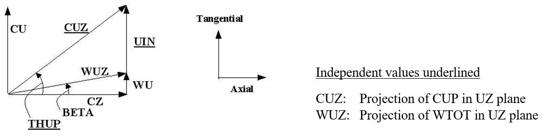
The following definitions apply to the variables of concern:
CUP: Magnitude of upstream chamber absolute flow velocity
THUP: Upstream chamber absolute tangential flow angle
TTUP: Upstream inertial chamber absolute total temperature
UIN: Reference frame (i.e. rotor) tangential velocity at the element inlet radius
WTOT: Magnitude of the flow velocity relative to the rotational reference frame (i.e. rotor) at the element inlet
BETA: Tangential flow angle relative to the rotational reference frame (i.e. rotor) at the element inlet
TTB: Total temperature relative to the rotational reference frame (i.e. rotor) at the element inlet
CU: Magnitude of upstream chamber absolute tangential flow velocity
CZ: Magnitude of upstream chamber absolute axial flow velocity
CR: Magnitude of upstream chamber absolute radial flow velocity
WU Magnitude of tangential fluid velocity relative to the rotational reference frame (i.e. rotor) at the element inlet
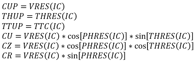
If the upstream chamber is chamber IC, the upstream absolute values are obtained directly from the chamber state:
The element motion is entirely in the tangential direction, so the axial and radial relative velocity components are the same as their respective absolute components:
WZ=CZ
WR=CR
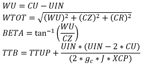
The reference frame (i.e. rotor) tangential velocity at the element inlet is calculated as
UIN=2π(RI/12)(RPMEL/60)
RPMEL: Input element rotational speed (rev/min)
RI: Radius from the engine centerline to the element inlet (in)
Based on the vector diagram shown below and making use of the Euler equation for the total relative fluid temperature, the remaining variables are calculated according to the equations:
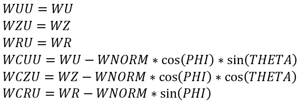
Approach Relative Angle and Crossflow Components
The approach relative angle is defined as the angle the relative velocity vector, WTOT, (made up of the components WU, WZ and WR) makes with the axis of the element restriction as defined by the element tangential angle, THETA, and the element radial angle, PHI. Both THETA and PHI are element input variables (or are assumed to be zero). First, the component of fluid velocity relative to the rotational reference frame (i.e. rotor) at the element inlet in the direction of the element axis is calculated as:
![]()
The relative approach angle is then simply:
![]()
The crossflow velocity terms are calculated from the velocity vectors already obtained as follows:
Upstream Pressure Calculation
The inlet total pressure, PTS, is the driving pressure for flow through the element restriction. This pressure is dependent upon the relative velocity ahead of the element restriction and on the value of inlet head loss variable, DQIN, specified for the element. For all element types except the CDCOMP orifice element, the relative velocity, WDYN, used is WNORM. For the CDCOMP element, the dynamic pressure effect is assumed to be due only to axial velocity so WDYN is set equal to WZ. The inlet total pressure is then calculated using the subsonic Mach number routine and the equation,
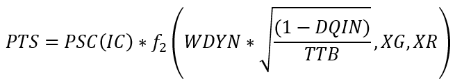
In performing this calculation, any negative value of DQIN is treated as DQIN = 0.0 if the upstream chamber is a plenum or momentum chamber and as DQIN = 1.0 if the upstream chamber is an inertial chamber.
Upstream Temperature Calculation
The inlet total relative temperature, TTS, is determined from the upstream total temperature, TTC, with modifications for reference frame changes. Basic to the understanding of these temperature adjustments is the assumption regarding the rotational state of the upstream chamber. Inertial chambers are by definition always in a stationary reference frame. Temperatures and velocities calculated for inertial chambers are therefore always absolute values, not relative values. Plenum and Momentum chambers are assumed to be rotating with whatever element they are attached to. Therefore, if a plenum or momentum chamber is attached to an element that is rotating at, for example, 14000 RPM, the chamber temperature will be considered to be the total relative temperature based on that RPM and the appropriate radius; the inlet radius for the upstream chamber and the outlet radius for the downstream chamber. If a Plenum or Momentum chamber is attached to two elements one of which is rotating at one RPM and the other at a different RPM (including 0 RPM), there will be an inconsistency in the interpretation of the temperature and velocity data for the chamber as the same values will represent relatives in two different reference frames. Therefore, for the proper interpretation of relative temperature and velocity, one must ensure that element RPM specified for each of the elements attached to any Plenum or Momentum chamber is the same. In the case of Vermes seal elements, which have potentially two rotor speeds, it is the speed of the “rotor” part, RPMSELR, that is used as the reference speed.
Employing these ground rules, if the upstream chamber type is Plenum or Momentum, then TTS is simply the upstream temperature chamber total temperature TTC. If the upstream chamber type is Inertial, the TTS is TTB as discussed above.
Computing Element Restriction Outlet Conditions
The element outlet flow conditions are the downstream information supplied to each element module for use in computing flow through the element. The back pressure is the principal parameter; however, crossflow velocities downstream of the element are included as well. For all element types discussed within this document, the downstream static pressure is used as the back pressure.
The analysis method of the element outlet flow condition is determined by the downstream chamber type. The variables required to define the outlet flow condition are:
PSEB: Outlet static pressure
WUD: Magnitude of tangential fluid velocity relative to the rotational reference frame (i.e. rotor) at the element exit
WRD: Magnitude of radial fluid velocity at the element exit
WZD: Magnitude of axial fluid velocity at the element exit
In Addition to the above the three components the three components of the crossflow velocity where crossflow is defined as the component of velocity perpendicular to the axis of the element
WCUD: Magnitude of tangential fluid velocity relative to the rotational reference frame (i.e. rotor) at the element exit perpendicular to the element axis
WCRD: Magnitude of radial fluid velocity at the element exit perpendicular to the element axis
WCZD: Magnitude of axial fluid velocity at the element exit perpendicular to the element axis
JC: Downstream Chamber
By definition, PSEB is simply the static pressure in the downstream:
PSEB=PSC(JC)
The downstream relative velocity and crossflow velocity terms are calculated in a manner similar to but much less involved than that used to calculate the upstream terms. For a downstream Momentum chamber, the downstream chamber Mach number is converted to a velocity using the Mach number function and values of and R obtained from the properties routine at TTC(JC), PSC(JC) and FS(JC):
![]()
For a downstream Plenum chamber, WDN is zero by definition. Directional components of velocity are then calculated as:
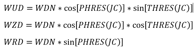
For a downstream Inertial chamber, the procedure uses the downstream chamber velocity, subtracting the tangential velocity of the element at its exit to get the relative tangential component:
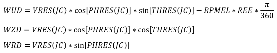
REE: Radius from the engine centerline to the element exit
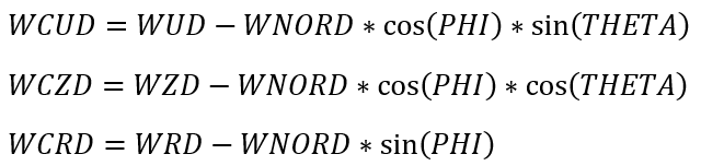
Based on the orientation of the element’s axis, as specified by the element input variables THETA and PHI (THTELX and PHIELX for Tube and Orifice elements), the component of fluid velocity relative to the rotational reference frame (i.e. rotor) at the element exit in the direction of the element axis is calculated as:
![]()
The crossflow velocity terms are calculated from the velocity vectors already obtained as follows:
Element Exit Flow State
As stated previously, the purpose of the element routines is to calculate the element flow rate, the exit flow state and element flow derivatives with respect to up and downstream pressure. The exit flow state defines the velocity, direction and temperature of the flow entering the downstream chamber from the element.
The exit flow state variables are all expressed in the coordinate reference frame of the chamber. The reference frame of inertial chambers is always absolute (stationary). In all other situations, the reference frame assumed for the chamber depends on the element for which the calculations are being made. If the element has no provision for rotation (i.e. no input for RPM and radius from the engine centerline) or the rotational speed of the element is set to zero, the downstream chamber is assumed to have the same rotational speed as the upstream chamber. For all other element types, the reference frame is assumed to be rotating at the primary rotor speed supplied for the element (i.e. if the element is a seal with two RPM input variables, the one defined by RPMSELR is used). Because a momentum or plenum chamber may have a number of elements connected to it, it is important that they all are referenced to the same rotational speed if consistent results are to be achieved. If they are not, the flows entering the chamber will be balanced out by Flow Simulator to satisfy continuity, but the temperatures and velocities supplied to recalculate the chamber conditions will be inconsistent. An inertial chamber must be used to connect elements with different rotational speeds.
While the element routines may or may not involve rotational effects, the routine for any element type is designed to return results with exit conditions expressed relative to a reference frame rotating with the element. The flow state quantities returned are the following:
SFE: Secondary fluid mass fraction of the element flow
TEX: Total temperature of the fluid relative to the rotational reference frame (i.e. rotor) at the element exit
PH: Radial flow angle at the element exit
THTA: Tangential flow angle relative to the rotational reference frame (i.e. rotor) at the element exit
VEX: Magnitude of the fluid velocity relative to the rotational reference frame (i.e. rotor) at the element exit
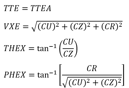
The variables required to be returned by the element routines to the Flow Simulator solver to specify the exit flow state are as defined in the section on ”Recalculating the Chamber State” If the downstream chamber is a Plenum or Momentum chamber, each of these variables will be as calculated by the element routine and the following equations for temperature, velocity and flow angles will apply:
TTE=TEX
VXE=VEX
PHEX=PH
THEX=THTA
Regardless of the existence of a downstream Inertial chamber FSE will remain unchanged.
Element Absolute Exit Flow State
Any element that has a downstream inertial chamber requires calculation of the absolute flow state leaving the restriction. If the element is not rotating, the absolute flow state is the same as the relative flow state and no additional computation is needed. If the element is rotating, the quantities that must be computed are the temperature and the absolute velocity. The process used is the inverse of the process discussed in the section on “Computing Element Inlet Conditions”. The following vector diagram applies.
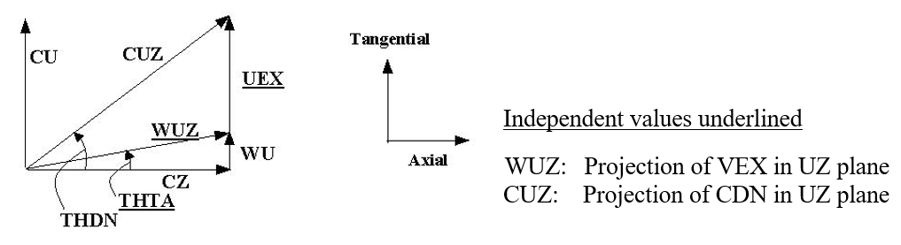
Figure:Velocity diagram for downstream absolute velocities
The first step is to calculate the three velocity components from the relative velocity and flow angles:
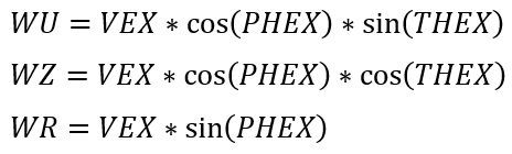
Since the relative motion is all due to rotation about the engine centerline, both WZ and WR are absolute as well as relative components of velocity.
Element rotational speed is the value input for the element, and UEX is calculated using the equation:
![]()
Whichever definition applies, the absolute tangential velocity is given by the equation:
CU=UEX+WU
and the absolute rotational velocity of the fluid becomes:
![]()
Turning next to the temperature, the convention in Flow Simulator when going from a rotating frame of reference to an absolute frame of reference is to use properties based on temperature in the absolute reference frame. Since the absolute temperature is not known when the present calculation process starts, the value of Cp used initially is the XCP evaluated at total relative temperature (TEX), secondary fluid mass fraction (FSE), and the back pressure (PSEB) used in the element flow calculation.
To obtain the absolute temperature as:
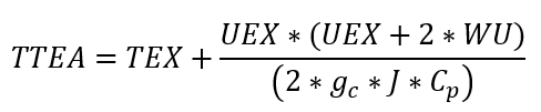
Since the Cp value used is to be determined at the absolute temperature, after the initial evaluation TTEA is calculated two more times with the value of Cp updated for the then current value of TTEA and this final value is returned to the calling routine.
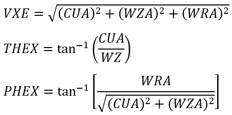
If the downstream chamber is an Inertial chamber, the exit flow conditions are simply the absolute flow state leaving the element:
If the downstream chamber is an Inertial chamber, the absolute tangential velocity is simply:
![]()
Since the axial and radial absolute velocity components are the same as the relative velocity components, the exit velocity and flow angles relative to the downstream chamber are then:
Element Outputs
The following table provides a description of Flow Simulator element output variables. The variables are listed in the order they appear as columns ‘.res’ file.
| Name | Description | Units ENG, SI |
|---|---|---|
| FLOW %WREF | Flow rate through the element as a percentage of WREF flow. | (%) |
| FLOW PPS | Flow rate through the element. | lbm/s, kg/s |
| DQIN |
Inlet dynamic head loss. (Usually an echo of the input unless modified inside Flow Simulator.) Refer General solver theory sections for more details about this input |
(fraction) |
| K_EXIT_Z |
Z-direction exit head loss. (Usually an echo of the input unless modified inside Flow Simulator.) If K_EXIT_Z is greater than 0 and less than or equal to 1.0, the exit velocity component in the direction defined by THETA = 0, PHI = 0 is recalculated as: (Default value = 0.) |
(fraction) |
| K_EXIT_U |
U-direction exit head loss. (Usually an echo of the input unless modified inside Flow Simulator.) If K_EXIT_U is greater than 0 and less than or equal to 1.0, the exit velocity component in the direction defined by THETA = 90, PHI = 0 is recalculated as: (Default value = 0.) |
(fraction) |
| K_EXIT_R |
R-direction exit head loss. (Usually an echo of the input unless modified inside Flow Simulator.) If K_EXIT_R is greater than 0 and less than or equal to 1.0, the exit velocity component in the direction defined by PHI = 90 is recalculated as: (Default value = 0.) |
(fraction) |
| ELEMENT_THETA |
Angle between the element centerline and the reference direction. (Usually an echo of the input unless modified inside Flow Simulator.) |
deg |
| ELEMENT_PHI |
Angle between the element centerline and the THETA direction. (Usually an echo of the input unless modified inside Flow Simulator.) |
deg |
| REL_INLET_ANGLE | Relative angle between the element centerline (as defined by THETA and PHI) and the resolved flow direction in the upstream chamber. | deg |
| ELEMENT_RPM | The rotational speed of the element. | rev/min |
| RAD | Radius to the element from the engine centerline. | inch. mm |
| ELEMENT_THETA_EXIT |
Angle between the element exit centerline and the reference direction. (Usually an echo of the input unless modified inside Flow Simulator.) |
deg |
| ELEMENT_PHI_EXIT |
Angle between the element exit centerline and the THETA direction. (Usually an echo of the input unless modified inside Flow Simulator.) |
deg |
The following table contains information about the new output variables appended to the end of the detailed element results entries for each element type (except the fixed flow element).
| Name | Description | Units ENG, SI |
|---|---|---|
| VABS | Absolute fluid velocity at the restriction inlet/exit, | ft/s. m/s |
| THTA_ABS | Angle between the absolute tangential (VTAN_ABS) and axial (VAXIAL) fluid velocity components at the restriction inlet/exit. | deg |
| VTAN_ABS |
Absolute tangential fluid velocity component at the restriction inlet/exit. Calculated as the sum of the tangential velocity of fluid relative to the reference frame (i.e. rotor) and the reference frame (i.e. rotor) tangential velocity. |
ft/s. m/s |
| VAXIAL |
Axial fluid velocity component at the restriction inlet/exit. FlowSimulator assumes no relative motion in the axial direction, so relative and absolute axial velocities are equal. |
ft/s. m/s |
| VRAD |
Radial fluid velocity component at the restriction inlet/exit. FlowSimulator assumes no relative motion in the radial direction, so relative and absolute radial velocities are equal. |
ft/s. m/s |
| VREL | Magnitude of the fluid velocity relative to the rotational reference frame (i.e. rotor) | ft/s. m/s |
| THTA_REL | Angle between the relative tangential (VTAN_REL) and axial (VAXIAL) fluid velocity components at the restriction inlet/exit. | ft/s. m/s |
| VTAN_REF | Tangential velocity of the rotational reference frame (i.e. rotor). | ft/s. m/s |
| VTAN_REL | Tangential fluid velocity relative to the rotational reference frame (i.e. rotor) at the restriction inlet/exit. | ft/s. m/s |
| VNORM | Component of the fluid velocity relative to the rotational reference frame at the restriction inlet/exit that is aligned with the restriction centerline. | ft/s. m/s |
| TTABS | Absolute total temperature of the fluid at the restriction inlet/exit. | deg F, K |
| TTREL | Total temperature of the fluid relative to the rotational reference frame (i.e. rotor). | deg F, K |