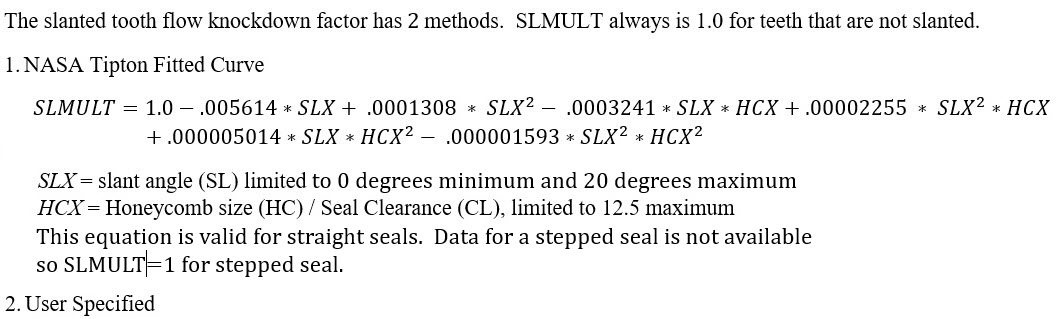
Vermes Seal Element
Description
The Vermes Seal element is typically used to model flow through labyrinth seals found in rotating machinery (gas turbines). The flow rate, swirl, and fluid temperature rise due to windage is calculated based on the seal geometry, and fluid conditions at the inlet and exit of the seal.
The seal clearance is the main dimension that controls the flow rate passing through the seal. It is the distance between the tip of the seal tooth and the opposite surface which is usually honeycomb. The seal clearance changes during gas turbine operation since the parts move due to temperature and rotation.
The Vermes seal element is based on the method of calculation of flow through labyrinth seals proposed in the paper by Geza Vermes (ref 1.)
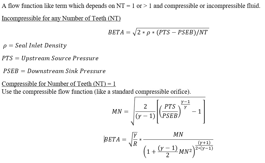
The element is typically used for compressible flow, but Flow Simulator can use this element with incompressible or compressible fluid.
Quick Guide for Vermes Seal Creation in the GUI
Vermes seal can be found under the “Compressible Gas Elements” - “Seals” section

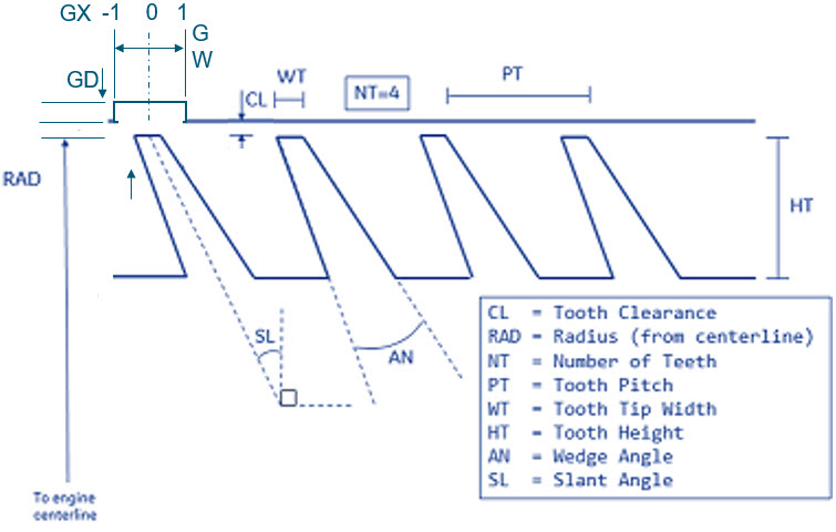
The figure below shows the geometric inputs. The seal clearance is the besides the geometric inputs the user needs to enter honeycomb information
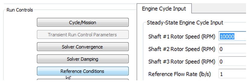
A Vermes seal typically has the seal teeth rotating. This requires the user to enter an RPM reference condition in the Solution Panel.
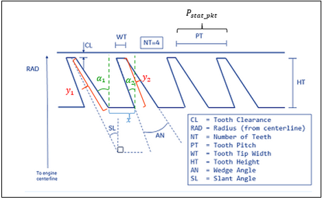
Vermes Seal Inputs
Table of the inputs for the Vermes seal. See the image in the user interface to understand geometric variables.
| Vermes Seal Element Input Variables | |||||||||||||||||||||||||||||||||||||||||||||||||||||||||||||||||||||||||||||||||||||||||||||||||||||||||||||||||||||||||||||||||||||||||||||||||||||||||||
| Index | UI Name (.flo label) | Description | |||||||||||||||||||||||||||||||||||||||||||||||||||||||||||||||||||||||||||||||||||||||||||||||||||||||||||||||||||||||||||||||||||||||||||||||||||||||||
| 1 | Seal Clearance (CL) | Seal clearance . | |||||||||||||||||||||||||||||||||||||||||||||||||||||||||||||||||||||||||||||||||||||||||||||||||||||||||||||||||||||||||||||||||||||||||||||||||||||||||
| 2 | Nominal Seal Radius or Inlet Radius (RAD) | Nominal seal radius for a straight seal or the inlet radius for a stepped seal. | |||||||||||||||||||||||||||||||||||||||||||||||||||||||||||||||||||||||||||||||||||||||||||||||||||||||||||||||||||||||||||||||||||||||||||||||||||||||||
| 3 | Number of Teeth (NT) | Number of teeth in seal. | |||||||||||||||||||||||||||||||||||||||||||||||||||||||||||||||||||||||||||||||||||||||||||||||||||||||||||||||||||||||||||||||||||||||||||||||||||||||||
| 4 | Seal Axial Pitch (PT) | Seal axial pitch . | |||||||||||||||||||||||||||||||||||||||||||||||||||||||||||||||||||||||||||||||||||||||||||||||||||||||||||||||||||||||||||||||||||||||||||||||||||||||||
| 5 | Tooth Tip Width (WT) | Axial width of seal tooth tip. | |||||||||||||||||||||||||||||||||||||||||||||||||||||||||||||||||||||||||||||||||||||||||||||||||||||||||||||||||||||||||||||||||||||||||||||||||||||||||
| 6 | Seal Tooth Height (HT) |
Seal tooth height . This variable influence only the windage calculated for a rotating seal. |
|||||||||||||||||||||||||||||||||||||||||||||||||||||||||||||||||||||||||||||||||||||||||||||||||||||||||||||||||||||||||||||||||||||||||||||||||||||||||
| 7 | Wedge Angle (AN) | Angle between sides of a seal tooth . | |||||||||||||||||||||||||||||||||||||||||||||||||||||||||||||||||||||||||||||||||||||||||||||||||||||||||||||||||||||||||||||||||||||||||||||||||||||||||
| 8 | Rotor Surf. Rot. Speed (RPMSELR) |
Rotational speed pointer of seal rotor surface. 0.0: Specifies a stationary element. 1.0: Points to general data ELERPM(1). 2.0: Points to general data ELERPM(2). 3.0: Points to general data ELERPM(3). |
|||||||||||||||||||||||||||||||||||||||||||||||||||||||||||||||||||||||||||||||||||||||||||||||||||||||||||||||||||||||||||||||||||||||||||||||||||||||||
| 9 | Slant Angle (SL) | Angle the tooth centerline makes with the radial direction.
Positive angle if tooth is angled into the flow and negative angle if slanted away from the flow. |
|||||||||||||||||||||||||||||||||||||||||||||||||||||||||||||||||||||||||||||||||||||||||||||||||||||||||||||||||||||||||||||||||||||||||||||||||||||||||
| 10 | Land Surf. Rot. Speed (RPMSELL) |
Rotational speed pointer of seal land surface. 0.0: Specifies a stationary element. 1.0: Points to general data ELERPM(1). 2.0: Points to general data ELERPM(2). 3.0: Points to general data ELERPM(3). |
|||||||||||||||||||||||||||||||||||||||||||||||||||||||||||||||||||||||||||||||||||||||||||||||||||||||||||||||||||||||||||||||||||||||||||||||||||||||||
| 11 | Seal Type (SEAT) |
Seal-Seat and Type Flag
|
|||||||||||||||||||||||||||||||||||||||||||||||||||||||||||||||||||||||||||||||||||||||||||||||||||||||||||||||||||||||||||||||||||||||||||||||||||||||||
| 12 | Portion of Ustrm Cham. Dyn. Head Lost (DQ_IN) |
Inlet dynamic head loss. If DQIN ≥ 0 and the upstream chamber has a positive component of relative velocity aligned with the axis of the tube, the driving pressure will be reduced by the equation: The default value of -1.0 will be interpreted by Flow Simulator as a flag to use only static pressure if the upstream chamber is an inertial chamber and a DQ_IN of 0 if the upstream chamber is a momentum chamber. |
|||||||||||||||||||||||||||||||||||||||||||||||||||||||||||||||||||||||||||||||||||||||||||||||||||||||||||||||||||||||||||||||||||||||||||||||||||||||||
| 13 | Element Alignment (AXIS_DIR) |
Direction of positive flow through the seal If AXIS_DIR ≥ 0, the axial direction for positive flow is assumed to be the direction defined by THETA = 0, PHI = 0. If AXIS_DIR < 0, the axial direction for positive flow is assumed to be the direction defined by THETA = 180, PHI = 0. |
|||||||||||||||||||||||||||||||||||||||||||||||||||||||||||||||||||||||||||||||||||||||||||||||||||||||||||||||||||||||||||||||||||||||||||||||||||||||||
| 14 | Laminar-Transitional Reynolds Number (RE_LAM) | Reynolds number below which pocket swirl flow is assumed to be laminar. Flow at Reynolds numbers between RE_LAM and RE_TURB are assumed to be in the transition region. Defaults to 2070 for Vermes Seal. | |||||||||||||||||||||||||||||||||||||||||||||||||||||||||||||||||||||||||||||||||||||||||||||||||||||||||||||||||||||||||||||||||||||||||||||||||||||||||
| 15 | Turbulent-Transitional Reynolds Number (RE_TURB) | Reynolds number above which pocket swirl flow is assumed to be turbulent. Flow at Reynolds numbers between RE_LAM and RE_TURB are assumed to be in the transition region. Defaults to 2530 for Vermes Seal. | |||||||||||||||||||||||||||||||||||||||||||||||||||||||||||||||||||||||||||||||||||||||||||||||||||||||||||||||||||||||||||||||||||||||||||||||||||||||||
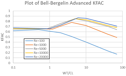
| 16 | Clearance Factor Method (KFAC_METHOD) | 0: Bell-Bergelin curve for CD of annular orifice (Default) 1: Bell-Bergelin Advanced, Table lookup for multiple Re (Default) -1: User-supplied KFAC, either constant value or calculated using controllers. See KFAC details below. |
|||||||||||||||||||||||||||||||||||||||||||||||||||||||||||||||||||||||||||||||||||||||||||||||||||||||||||||||||||||||||||||||||||||||||||||||||||||||||
| 17 | Kinetic Energy Carryover Method (KE_METHOD) |
0: Vermes 1961 Kinetic Energy Carryover curve 1: Morrison Kinetic Energy Carryover curve 2: Minimum of Vermes and Morrison curves (Default, matches NASA Tipton data best) 3: Saikishan-Morrison -1: User supplies their own KEMULT, either constant value or calculated using controllers. See KEMULT details below. 4: Neumann Kinetic Energy Carryover curve |
|||||||||||||||||||||||||||||||||||||||||||||||||||||||||||||||||||||||||||||||||||||||||||||||||||||||||||||||||||||||||||||||||||||||||||||||||||||||||
| 18 | Honeycomb Method (HC_METHOD) | Auto, Tipton/Schramm Method (Default) – Tipton for Straight
Seals, Schramm for Stepped Seals. 2: Stocker curve for straight seals. 3: Schramm curve for stepped seals. 4: Tipton table lookup for straight seals. -1: User supplies their own HCMULT, either constant value or calculated using controllers. See HCMULT details below. |
|||||||||||||||||||||||||||||||||||||||||||||||||||||||||||||||||||||||||||||||||||||||||||||||||||||||||||||||||||||||||||||||||||||||||||||||||||||||||
| 19 | Slanted Teeth Method (SL_METHOD) |
1: Curve fitted to NASA Tipton data -1: User supplies their own SLMULT, either constant value or calculated using controllers. See SLMULT details below. |
|||||||||||||||||||||||||||||||||||||||||||||||||||||||||||||||||||||||||||||||||||||||||||||||||||||||||||||||||||||||||||||||||||||||||||||||||||||||||
| 20 | Honeycomb Size (HCSIZE) | Honeycomb Size – Standard choices are 1/32”, 1/16”, and 1/8”. However, it is possible to input a custom honeycomb size. Solver units are inches. | |||||||||||||||||||||||||||||||||||||||||||||||||||||||||||||||||||||||||||||||||||||||||||||||||||||||||||||||||||||||||||||||||||||||||||||||||||||||||
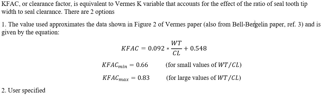
| 21 | Clearance Factor (KFAC) | Clearance factor is the Discharge Coefficient of a single annular orifice or tooth gap. The value is between 0 and 1, usually between 0.6 and 0.9. See Vermes 1961 or Bell-Bergelin. | |||||||||||||||||||||||||||||||||||||||||||||||||||||||||||||||||||||||||||||||||||||||||||||||||||||||||||||||||||||||||||||||||||||||||||||||||||||||||
| 22 | Kinetic Energy Carryover Factor (KEMULT) | Kinetic Energy Carryover Factor is a value from 1 to about 2.4. It accounts for axial momentum and energy that is retained as flow goes around a tooth. A value of 1 means the tooth blocked all kinetic energy. A value higher than 1 implies some kinetic energy was carried over. Please see Vermes 1961, Morrison, and Alexiou for details. | |||||||||||||||||||||||||||||||||||||||||||||||||||||||||||||||||||||||||||||||||||||||||||||||||||||||||||||||||||||||||||||||||||||||||||||||||||||||||
| 23 | Honeycomb Flow Multiplier (HCMULT) | Honeycomb Flow Knockdown Factor is a multiplier that is applied to non-honeycomb leakage flow to calculate the corrected leakage flow with a honeycomb stator. Typical values are from 0.8 to 1.2. Values less than one imply the honeycomb is supplying an additional source of resistance, which is often true for straight seals. Values greater than one imply that the honeycomb is creating a new path for leakage flow, which is often true for stepped seals. Please see Stocker and Schramm for additional details. | |||||||||||||||||||||||||||||||||||||||||||||||||||||||||||||||||||||||||||||||||||||||||||||||||||||||||||||||||||||||||||||||||||||||||||||||||||||||||
| 24 | Slant Flow Multiplier (SLMULT) | Slanted Teeth Flow Knockdown Factor is a multiplier that is applied to straight-tooth leakage flow to calculate the corrected leakage flow with slanted teeth. Typical values are from 0.85 to 1.1. Three-dimension flows in seal pockets are complex, and it is difficult to explain why the factor is sometimes less than one and sometimes greater. | |||||||||||||||||||||||||||||||||||||||||||||||||||||||||||||||||||||||||||||||||||||||||||||||||||||||||||||||||||||||||||||||||||||||||||||||||||||||||
| 25 | Swirl Carryover Factor per Tooth (ETATOOTH) | Swirl Carryover per Tooth is the fraction of tangential fluid velocity (relative to the stator) that passes each tooth and enters the next pocket. This is a calibration parameter that helps to match the correct swirl and windage heating. It is especially useful for stepped honeycomb seals where the air passes over the tooth and immediately impinges on the honeycomb step. | |||||||||||||||||||||||||||||||||||||||||||||||||||||||||||||||||||||||||||||||||||||||||||||||||||||||||||||||||||||||||||||||||||||||||||||||||||||||||
| 26 |
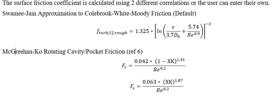
Friction and Windage – Rotor: Friction Relation (FRIC_REL_R) |
0: Swamee-Jain Approximation to Colebrook-White-Moody Friction (Default) 1: MacGreehan-Ko Rotating Cavity/Pocket Friction 5: Sultanian -1: User supplies FRICF_STATOR, either constant value or calculated using controllers. See FRICF_STATOR details below. |
|||||||||||||||||||||||||||||||||||||||||||||||||||||||||||||||||||||||||||||||||||||||||||||||||||||||||||||||||||||||||||||||||||||||||||||||||||||||||
| 27 | Rotor Sandgrain Roughness (ROUGH_ROTOR) | Roughness of the rotor surface. It is assumed to be a sand-grain type roughness, which is consistent with Colebrook-White-Moody. | |||||||||||||||||||||||||||||||||||||||||||||||||||||||||||||||||||||||||||||||||||||||||||||||||||||||||||||||||||||||||||||||||||||||||||||||||||||||||
| 28 |
Friction and Windage – Rotor: Friction Multiplier (F_MULT_ROTOR) |
Friction multiplier on Rotor is used if you want the friction curve to follow that same basic trend as Swamee-Jain or MacGreehan-Ko but your custom friction curve differs by a multiplication factor. | |||||||||||||||||||||||||||||||||||||||||||||||||||||||||||||||||||||||||||||||||||||||||||||||||||||||||||||||||||||||||||||||||||||||||||||||||||||||||
| 29 |
Friction and Windage – Rotor: Friction Coefficient (FRICF_ROTOR) |
Fanning Friction Coefficient on Rotor can be supplied as a constant value, or it can be calculated using a controller. | |||||||||||||||||||||||||||||||||||||||||||||||||||||||||||||||||||||||||||||||||||||||||||||||||||||||||||||||||||||||||||||||||||||||||||||||||||||||||
| 30 |
Friction and Windage – Rotor: Total Rotor Surface Area (ASR) |
Generally, ASR=0 and the rotor friction area is calculated from other geometric inputs such as tooth height, spacing, wedge angle, slant angle, etc. If you enter a non-zero value, your input will override the calculated area. Solver units are sq.in. | |||||||||||||||||||||||||||||||||||||||||||||||||||||||||||||||||||||||||||||||||||||||||||||||||||||||||||||||||||||||||||||||||||||||||||||||||||||||||
| 31 |
Friction and Windage – Stator: Friction Relation (FRIC_REL_S) |
0: Swamee-Jain Approximation to Colebrook-White-Moody Friction (Default) 1: MacGreehan-Ko Rotating Cavity/Pocket Friction 5: Sultanian -1: User supplies FRICF_STATOR, either constant value or calculated using controllers. See FRICF_STATOR details below. |
|||||||||||||||||||||||||||||||||||||||||||||||||||||||||||||||||||||||||||||||||||||||||||||||||||||||||||||||||||||||||||||||||||||||||||||||||||||||||
| 32 | Stator Sandgrain Roughness (ROUGH_STATOR) | Roughness of the stator surface. It is assumed to be a sand-grain type roughness, which is consistent with Colebrook-White-Moody. Estimating a suitable roughness for a honeycomb surface is one challenge, but no advice can be given here. | |||||||||||||||||||||||||||||||||||||||||||||||||||||||||||||||||||||||||||||||||||||||||||||||||||||||||||||||||||||||||||||||||||||||||||||||||||||||||
| 33 |
Friction and Windage – Stator: Friction Multiplier (F_MULT_STATOR) |
Friction multiplier on Stator is used if you want the friction curve to follow that same basic trend as Swamee-Jain or MacGreehan-Ko but your custom friction curve differs by a multiplication factor. | |||||||||||||||||||||||||||||||||||||||||||||||||||||||||||||||||||||||||||||||||||||||||||||||||||||||||||||||||||||||||||||||||||||||||||||||||||||||||
| 34 |
Friction and Windage – Stator: Friction Coefficient (FRICF_STATOR) |
Fanning Friction Coefficient on Stator can be supplied as a constant value, or it can be calculated using a controller. | |||||||||||||||||||||||||||||||||||||||||||||||||||||||||||||||||||||||||||||||||||||||||||||||||||||||||||||||||||||||||||||||||||||||||||||||||||||||||
| 35 |
Friction and Windage – Stator: Total Land Surface Area (ASS) |
Generally, ASR=0 and the rotor friction area is calculated from other geometric inputs such as tooth height, spacing, wedge angle, slant angle, etc. If you enter a non-zero value, your input will override the calculated area. This is especially useful for stepped seals, since the current Vermes Seal element does not have a step height input. However, it could be better to ignore the step height and rely on ETATOOTH – please see above. Solver units are sq.in. | |||||||||||||||||||||||||||||||||||||||||||||||||||||||||||||||||||||||||||||||||||||||||||||||||||||||||||||||||||||||||||||||||||||||||||||||||||||||||
| 36 | (CL_TABLE) | Number of entries in the CL_VALUES table. | |||||||||||||||||||||||||||||||||||||||||||||||||||||||||||||||||||||||||||||||||||||||||||||||||||||||||||||||||||||||||||||||||||||||||||||||||||||||||
| 37 | Groove Depth (GRV_DEPTH) |
Depth of the groove (GD) in the honeycomb (or other land material) | |||||||||||||||||||||||||||||||||||||||||||||||||||||||||||||||||||||||||||||||||||||||||||||||||||||||||||||||||||||||||||||||||||||||||||||||||||||||||
| 38 | Groove Width (GRV_WIDTH) |
Width of the groove (GW) in the honeycomb (or other land material) | |||||||||||||||||||||||||||||||||||||||||||||||||||||||||||||||||||||||||||||||||||||||||||||||||||||||||||||||||||||||||||||||||||||||||||||||||||||||||
| 39 | Groove Tooth Axial Position (GRV_AX) |
Location of the tooth in the groove. 0 = tooth in the center of the groove -1 = tooth hitting left edge of groove 1 = tooth hitting right edge of groove Used for the Minimum Clearance method. |
|||||||||||||||||||||||||||||||||||||||||||||||||||||||||||||||||||||||||||||||||||||||||||||||||||||||||||||||||||||||||||||||||||||||||||||||||||||||||
| 40 | Groove Multiplier (GRV_MULT) |
Groove Flow Knockdown Factor is a multiplier that is applied to a no-groove leakage flow to calculate the leakage flow with a groove. Can be greater or less than 1. If the tooth is outside the groove, GRV_MULT should be > 1 indicating more flow through the seal. | |||||||||||||||||||||||||||||||||||||||||||||||||||||||||||||||||||||||||||||||||||||||||||||||||||||||||||||||||||||||||||||||||||||||||||||||||||||||||
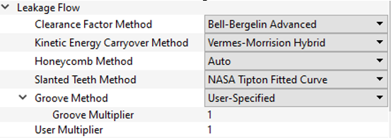
| 41 | Groove Method (GRV_METHOD) |
Method to use to calculate the groove effect. -1 = User Specified GRV_MULT 1 = Zimmerman Method 2 = Minimum Clearance |
|||||||||||||||||||||||||||||||||||||||||||||||||||||||||||||||||||||||||||||||||||||||||||||||||||||||||||||||||||||||||||||||||||||||||||||||||||||||||
| 42 | User Multiplier (USRMULT) |
A user supplied flow knockdown factor. Can be used with a controller for general purpose effects if needed. | |||||||||||||||||||||||||||||||||||||||||||||||||||||||||||||||||||||||||||||||||||||||||||||||||||||||||||||||||||||||||||||||||||||||||||||||||||||||||
| 43 | Exit Radius (RAD_EX) |
The exit radius for a stepped seal. | |||||||||||||||||||||||||||||||||||||||||||||||||||||||||||||||||||||||||||||||||||||||||||||||||||||||||||||||||||||||||||||||||||||||||||||||||||||||||
| 44 | Pocket Heat Transfer Option – Rotor (HTOPT_ROTOR) | The heat transfer option to use on the rotor surface in each
pocket. 0: No Heat Transfer (default) 1: Heat Transfer ON with a constant HTC 2: Heat Transfer ON with a constant Q >1000: Heat Transfer ON with a custom HTC correlation (ROTATING_CAVITY_NU) |
|||||||||||||||||||||||||||||||||||||||||||||||||||||||||||||||||||||||||||||||||||||||||||||||||||||||||||||||||||||||||||||||||||||||||||||||||||||||||
| 45 | Pocket Heat Transfer Option – Stator (HTOPT_STATOR) | The heat transfer option to use on the stator surface in each pocket. Same options as rotor surface of pocket. | |||||||||||||||||||||||||||||||||||||||||||||||||||||||||||||||||||||||||||||||||||||||||||||||||||||||||||||||||||||||||||||||||||||||||||||||||||||||||
| Table 1 | Individual Tooth Clearances (CL_VALUES) | There is an option to provide an array of individual clearance
values, one for each seal tooth. The method uses a curve that is
fitted to Tisarev, Falaleev, Vinogradov 2014 data, and computes an
effective tooth clearance from the array of individual tooth
clearance values. Solver units are inches. The following equation
is used to calculate and effective clearance for the entire
seal. |
|||||||||||||||||||||||||||||||||||||||||||||||||||||||||||||||||||||||||||||||||||||||||||||||||||||||||||||||||||||||||||||||||||||||||||||||||||||||||
| HTC or Q Tables | (ROTOR_PKT_HTC_OR_Q), (STATOR_PKT_HTC_OR_Q) | A constant Heat Transfer Coefficient (HTC), BTU/(hr ft^2 F) or
constant heat addition (Btu/sec). Separate tables for Rotor and Stator. One entry for each pocket. The table only exists when needed for the heat transfer option. |
|||||||||||||||||||||||||||||||||||||||||||||||||||||||||||||||||||||||||||||||||||||||||||||||||||||||||||||||||||||||||||||||||||||||||||||||||||||||||
| Wall Temperature Tables | (ROTOR_PKT_TWALL), (STATOR_PKT TWALL) | The wall temperature to us pocket heat transfer (deg
F). Separate tables for Rotor and Stator. One entry for each pocket. The table only exists when needed for the heat transfer option. |
|||||||||||||||||||||||||||||||||||||||||||||||||||||||||||||||||||||||||||||||||||||||||||||||||||||||||||||||||||||||||||||||||||||||||||||||||||||||||
Vermes Seal Theory
Flow Rate Calculation
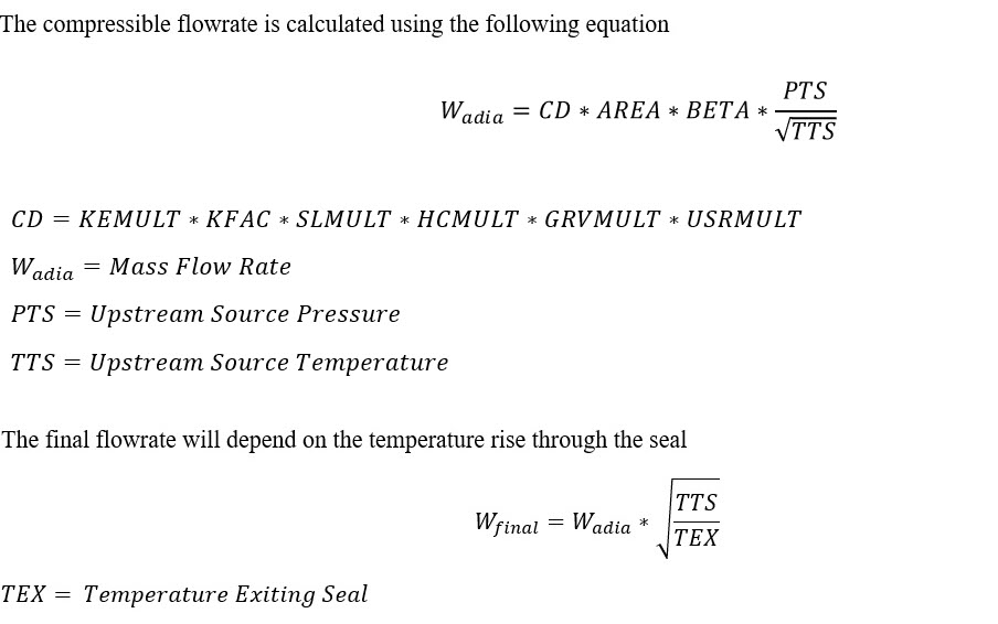
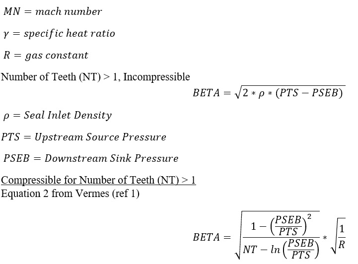
For a seal with one tooth, KEMULT=1.0, and BETA is calculated using the flow function. See the BETA section for details.
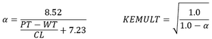
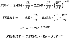
KEMULT
- Vermes
- Morrison (Ref 2, eq 5)
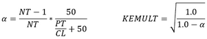
- Vermes-Morrison
Use the minimum alpha from 1 and 2.
- User-specified KEMULT.
- SAIKISHAN_MORRISON (Ref 2, eq 7)
This method uses the flow Re to calculate the KEMULT. Since the flow Re depends on the flow through the seal, this method uses the flow from the previous iteration.
- Neumann (Ref 10)
KFAC
SLMULT
HCMULT
- Auto method uses Tipton table for straight seals and Schramm equation for stepped seals. This is the default.
- Schramm Stepped Seal (Ref 4, Fig 12).
- Stocker Straight (Ref 4, Fig 12)
- Tipton Straight (Ref 7, Fig 26). An HCMULT is calculated using bilinear
interpolation of the curves shown here.
Figure 4. 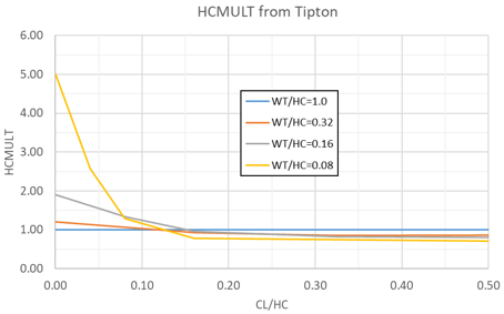
- User Specified.
GRVMULT
The flow knockdown factor is due to a groove in the honeycomb.
- -1: User supplied.
- 1: Based on Zimmermann (Fig 7 in reference 8).
Figure 5. 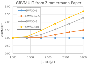
The groove width/groove depth (GW/GD) is limited in the solver to between 1 and 10. The (groove depth + clearance)/clearance ((GD+CL)/CL) is limited in the solver to between 1 and 3. Valid for Re>5000, GW/GD>2.5, but correlation uses GW/GD=1 curve also. The tooth must be outside of the honeycomb groove to use the Zimmermann data.
- Minimum Clearance
This option is useful when the tooth is inside of the honeycomb groove and the Zimmermann method is not applicable. When the tooth is inside the groove, the clearance can be entered as a negative number if the groove method uses the minimum clearance. This method calculates a new clearance, CL, based on the minimum distance between the tooth and the grove bottom, or sides. The minimum clearance is then used in all other equations for the seal losses and areas, but the GRVMULT=1.
Examples where the arrow represents the minimum clearance:Figure 6. 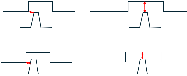
AREA
![]()
BETA
 .
.
Choked Flow Calculation
For compressible gasses, the calculated seal mass flow is compared to the mass flow for choked flow through the last tooth. If the choked flow through the last tooth is less than the calculated seal mass flow, the choked flow is used. The equations for the choked flow calculation are:
Where:
This accounts for the additional flow area if the honeycomb cell allows the seal to flow more than a smooth surface (HCMULT>1 if the clearance is small and HC size is large).
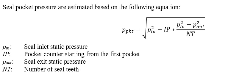
Calculation of Seal Pocket Pressure
Calculation of Seal Pocket Swirl
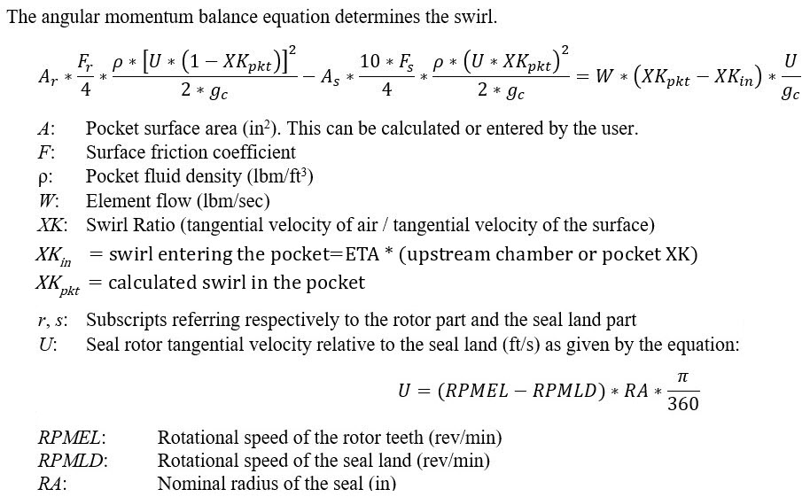
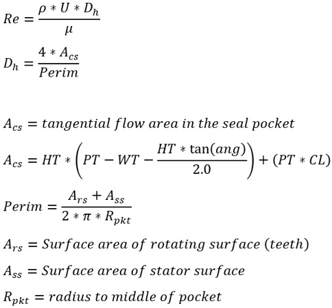
The seal “rotor” surface area is calculated using the following:
Surface area per pocket:
Where:
Surface area for all pockets:
The vermes seal “stator” surface area is calculated using the following:
Surface area per pocket:
Where:
Surface area for all pockets:
Sultanian Friction (ref 9)
Rotor Surface:
Stator Surface:
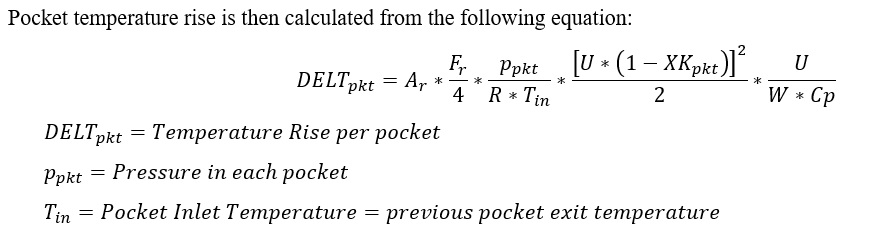
Calculation of Seal Windage Temperature Rise
Seal Pocket Heat Transfer
In addition to the fluid temperature change due to windage, the fluid temperature can also change due to the fluid convection to the pocket surface. The convection Q is applied at each pocket. The typical convection heat transfer equation is used.
HTC = heat transfer coefficient supplied by the user or calculated by the correlation.
Area = pocket surface area.
Tsurf = the surface temperature supplied by the user.
Tfluid rel = the relative fluid total temperature, adjusted for fluid and surface rotation.
Vermes Seal Outputs
Outputs in file with “res” extension. Output units controlled by user setting in “Output Control” panel.

| Name | Description | Units ENG, SI |
|---|---|---|
|
SEAL_POSITIVE_ FLOW_DIRECTION |
Direction of positive flow through the seal. 1: Axial direction for positive flow is assumed to be the direction defined by THETA = 0, PHI = 0. -1: Axial direction for positive flow is assumed to be the direction defined by THETA = 180, PHI = 0. |
None |
| SEAL TYPE | Seal type flag. | None |
| SEAL | Seal land type (STRAIGHT or STEPPED). | None |
| SEAT | Seal seat type (SOLID, 1/32 HEX, 1/16 HEX, or , 1/8 HEX). | None |
| TOOTH | Seal tooth type (STRAIGHT or SLANT). | None |
| CL | Seal clearance. This is an effective clearance if more than 1 tooth clearance is provided. | Inch,mm |
| RAD | Nominal seal radius. Distance from engine centerline to the seal tooth tip. | Inch,m |
| WT | Axial width of seal tooth tip. | Inch,mm |
| PT | Seal axial pitch. | Inch,mm |
| NO_TEETH | Number of seal teeth. | (number) |
| HT |
Seal tooth height. This variable influences only the windage calculated for a rotating seal. |
Inch,mm |
| K/E_RPM | Rotational speed of the rotor surface. | rev/min |
| LAND_RPM | Rotational speed of the land surface. Also referred to as “stator”. | rev/min |
| DT | Absolute total temperature rise across the seal. | deg F,k |
| TEX | Absolute total temperature at the exit of the seal. | deg F,k |
| XKABS_IN | Swirl ratio entering the seal. Swirl in the absolute frame of reference. | None |
| XKABS_OUT | Swirl ratio exiting the seal. Swirl in the absolute frame of reference. | None |
| ASR_TOTAL | Rotor surface area | In^2,m^2 |
| ASS_TOTAL | Stator (aka Land) surface area | In^2,m^2 |
| DH_POCKET | Hydraulic diameter of the seal pockets. Assume each pocket is same. | Inch,mm |
| KFAC | Calculated clearance factor | None |
| KEMULT | Calculated kinetic energy carryover factor | None |
| HCMULT | Calculated Honeycomb Flow Knockdown Factor | None |
| SLMULT | Calculated slanted tooth flow knockdown factor | None |
| XKrel | Swirl ratio in each pocket. Swirl relative to the land, which is usually stationary. If the land is stationary XKrel is in the absolute frame of reference. | None |
| WIND. | Windage in each pocket | BTU/s,W |
| ReynR | Reynolds number relative to the rotor surface | None |
| FricFannR | Fanning Friction factor on the rotor surface | None |
| ReynS | Reynolds number relative to the stator surface | None |
| FricFannS | Fanning Friction factor on the stator surface | None |
| MACH NO. | The Mach number of the flow in the tooth gap. Based on physical area times HCMULT if greater than 1.0. | None |
| Re | Reynolds number of the flow in the tooth gap.
|
None |
Vermes Seal Validation
The Vermes seal results were compared to results from Tipton et.al. (ref 7).
Geometries
Number of teeth: 1, 3, 4, 5, 6, 10, 18
Step Height(in): -0.12, 0, +0.12
Honeycomb (in): Solid, 1/32, 1/16, 1/8
Tooth Slant Angle (deg): 0 , 20, 40, 42.5
Tooth Wedge Angle (deg): 0, 10, 14, 15, 19
Tooth Spacing (in): 0.1, 0.177, 0.179, 0.25, .30, .354, .378, .626
Tooth Height (in): 0.1, 0.126, 0.135, 0.17, 0.25, 0.5
Tooth Tip Radius (in): 2.0, 2.26, 3.0, 3.36, 5.0, 7.63
Clearances (in): .004, to .061
Geometry Ratios:
Pitch/Clearance: 4 to 156
Width/Clearance: .25 to 62.75
Width/Pitch: .031 to .67
Width/Honeycomb Size: .08 to .48
Clearance/Honeycomb Size: .04 to .65
Operating Conditions:
Pressure Ratio: 1.04 to 6.8
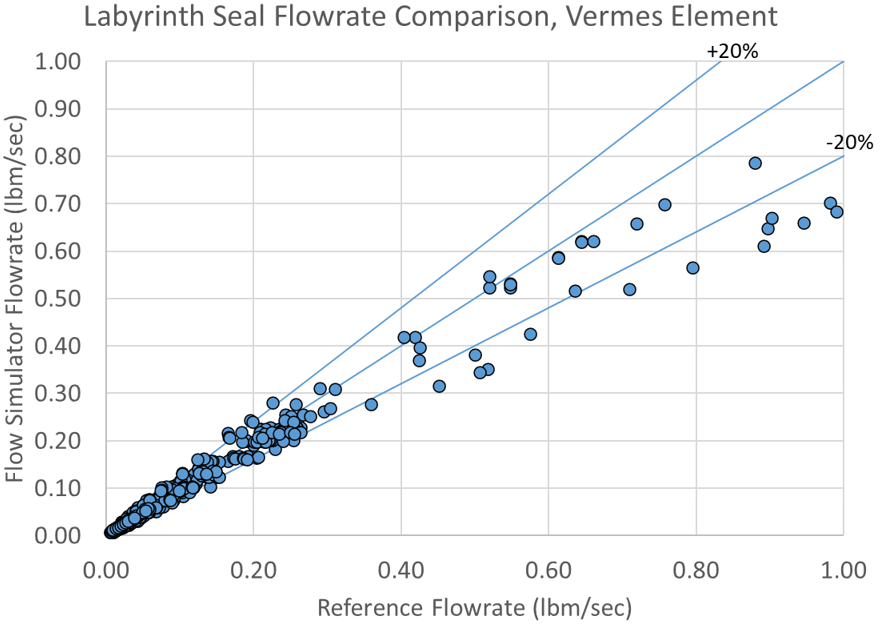

471 out of 705 test cases match within 10%
Vermes Seal References
- Vermes, Geza, "A Fluid Mechanics Approach to the Labyrinth Seal Leakage Problem", Transactions of the ASME, Journal of Engineering for Power, April 1961, pp161-169.
- Suryanarayanan, S & Morrison G.L "Labyrinth Seal Discharge Coefficient for Rectangular Cavities", ASME 2009.
- K.J. Bell & O.P. Bergelin, "Flow Through Annular Orifices", ASME 1957.
- Schramm V., Willenborg K., Kim S., Wittig S., "Influence of a Honeycomb Facing on the Flow Through a Stepped Labyrinth Seal", ASME 2002.
- Stocker, H. L., 1978, "Determining and Improving Labyrinth Seal Performance in Current and Advanced High Performance Gas Turbines", AGARD CP273.
- McGreehan W.F., & Ko S.H.,1989, "Power Dissipation in Smooth and Honeycomb Labyrinth Seals", ASME Paper No 89-FT-220.
- Tipton D.L., Scott T.E, Vogel R.E., 1986, "Labyrinth Seal Analysis. Volume 3. Analytical and Experimental Development of a Design Model for Labyrinth Seals", AFWAL-TR-85-2103.
- Zimmermann H., Wolff K. H., "Air System Correlations Part 1: Labyrinth Seals", ASME 98-GT-206.
- Bijay K. Sultanian, "Gas Turbines – Internal Flow Systems Modeling", Cambridge Aerospace series, 2018, ISBN 978-1-107-17009-4.
- Eldin, A. M. G., “Leakage and Rotordynamic Effects of Pocket Damper Seals and See-Through Labyrinth Seals”, Texas A&M Dissertation, 2007.