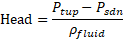
Effective Area Orifice Elements
Description
The Effective Area Orifice Element is like Orifice element and the value of the discharge coefficient or loss coefficient is a function of the orifice pressure ratio or orifice pressure drop. The orifice may be fixed in space or rotating about the engine centerline, and each may be positioned at any angle relative to the coordinate system. Effective area Orifice elements uses an input of Orifice mechanical Area/Diameter & Loss parameters with a standard isentropic flow relationship to calculate the element flow rates. This element does not model any fluid inertia.

Quick Guide for Effective Area Orifice Element Creation in the GUI
There are different subtypes of Effective Area Orifices elements available in Flow Simulator. All the orifice elements can be used in Compressible (e.g. gas systems) and Incompressible (e.g. hydraulic and non-hydraulic systems) analysis. The various subtypes are
- Cd vs. Pressure Ratio
- Pressure Ratio is the RATIO of the upstream driving pressure to the
downstream sink pressure.

- Pressure Ratio is the RATIO of the upstream driving pressure to the
downstream sink pressure.
- Cd vs. Delta-P

- Delta-P table is the DIFFERENCE between the upstream driving pressure
and downstream sink pressure
- Delta-P table is the DIFFERENCE between the upstream driving pressure
and downstream sink pressure
- Cd vs. Reynolds Number


- Where
- W = Mass Flow Rate

- If Hydraulic Diameter is provided, then

If Hydraulic Diameter or Perimeter is not Provided, Reynolds number is calculated based on Orifice Area
- Louver Element (Velocity vs. Delta.P)

- Delta-P table is the DIFFERENCE between the upstream driving pressure and downstream sink pressure. The Reference area for Velocity Calculation is based on user input for Curve Reference.
- If the user defined loss curve is based on Face Area, then the Face Area is used as reference to calculate Velocity. If the curve is based on Free Area, then reference area is calculated as (Face Area * Efficiency).
- If Reference Density is provided, then the Delta-P curve is scaled by a parameter (Fluid Density / Reference Density). The Flowrate is calculated based on incompressible assumption.
- K vs. Reynolds Number

- Where
- W = Mass Flow Rate
- If Hydraulic Diameter is provided, then
If Hydraulic Diameter or Perimeter is not Provided, Reynolds number is calculated based on Orifice Area
- Flow Func (FF) vs. Pressure Ratio (Ejector Arm)

- Pressure Ratio table is the RATIO of the upstream driving pressure to the downstream sink pressure.
- Cd vs. Pressure Parameter
- Pressure Parameter table is defined as a dynamic head ratio between upstream and downstream flow.
- Valve with K Table

- VALVE POS table is the position of a valve in whatever units the user determines, and the K-LOSS table is the inlet head loss
- Valve with Cd Table

- VALVE POS table is the position of a valve in whatever units the user determines, and the CD table is the compressible discharge coefficient
- Flow vs. Delta-P
- Delta-P table is the DIFFERENCE between the upstream driving pressure and downstream sink pressure
- Flow vs. Source Pressure
- Source Pressure is defined as the total pressure in the upstream chamber
- The upstream chamber is from the user defined flow direction so the element does not work with reversed flow.
- Flow vs. Delta-p vs. T

- Delta-P table is the DIFFERENCE between the upstream driving pressure and downstream sink pressure
- T is the defines as Upstream Total Temperature. This Element used to model Heat Exchange Systems
- Flow vs. Exit Static Pressure

- Exit Static Pressure is the static pressure in the downstream chamber.
- The downstream chamber is from the user defined flow direction so the element does not work with reversed flow.
- Flow vs. Exit Total Pressure

- Exit Total Pressure is the total pressure in the downstream chamber.
- The downstream chamber is from the user defined flow direction so the element does not work with reversed flow.
- Flow vs. Source Pressure vs. Exit Static Pressure

- Source Pressure is defined as the element driving pressure.
- Exit Static Pressure is the static pressure in the downstream chamber.
- The upstream and downstream ends are fixed based on the user defined flow direction so the element does not work with reversed flow.
- Swing Check Valve (Velocity vs Head Loss)

- Head Loss table is the HEAD between the upstream driving pressure and downstream sink pressure
Effective Area Orifice Element Inputs
| Element Specific Effective Area Orifice Element Input Variables | ||
|---|---|---|
| Index | UI Name (.flo label) | Description |
| 1 | Subtype (SUB_TYPE) |
The subtype of this element. Determines how flow is calculated
based on user input. 1: Cd vs. Pressure Ratio element 2: Cd vs. Delta-P element 3: Cd vs. Pressure Parameter element 4: Flow vs. Delta-P element 5: Valve with K-table element 6: Valve with Cd-table element 7: K vs. Reynolds Number element 8: Cd vs. Reynolds Number element 9: Flow vs. Source Pressure element 10: Flow Function vs. Pressure Ratio (Ejector Arm) element 12: Swing Check Valve Element 14: Flow vs. Sink Static Pressure 15: Flow vs. Sink Total Pressure 16: Flow vs. Delta-P vs. T element 17: Louver element 18: Flow vs Source Pressure vs. Sink Static Pressure |
| 2 | Area (Area) | Orifice mechanical area. A diameter can also be entered in the UI
and an area based on a circular hole is calculated. Flow is calculated based on an effective orifice area of (AREA* CD) with CD evaluated from the table of curves according to the subtype. It is recommended that AREA represent physical area and CD range from zero to one. Valve modeling should use a physical area based on valve position rather than the full open area. |
| 3 | (EXIT_XFLOW) | Not Used |
| 4 | Element Inlet Orientation: Tangential Angle (THETA) | Angle between the element centerline at the entrance of the
element and the reference direction. If the element is rotating or directly connected to one or more rotating elements, the reference direction is defined as parallel to the engine centerline and the angle is the projected angle in the tangential direction. Otherwise, the reference direction is arbitrary but assumed to be the same as the reference direction for all other elements attached to the upstream chamber. THETA for an element downstream of a plenum chamber has no impact on the solution except to set the default value of THETA_EX. (See also THETA_EX) |
| 5 | Element Inlet Orientation: Radial Angle (PHI) | Angle between the element centerline at the entrance of the
element and the THETA direction. (Spherical coordinate system)
PHI for an element downstream of a plenum chamber has no impact on the solution except to set the default value of PHI_EX. (See also PHI_EX) |
| 6 | Radius (RAD) | Radius. Radial distance between the orifice inlet center and the
engine centerline. (Do not use zero unless the orifice is not rotating) |
| 7 | (CURVE_NUM) | Not Used |
| 8 | Rotor Index (RPMSEL) |
Element rotational speed pointer. 0.0: Specifies a stationary element. 1.0: Points to general data ELERPM(1). 2.0: Points to general data ELERPM(2). 3.0: Points to general data ELERPM(3). -1.0: Element RPM is based on upstream fluid RPM. |
| 9 | Heat Input (QIN) | The value entered for QIN depends on the HEAT_MODE chosen. See Element Heat Addition for more information. |
| 10 | (NPRCD) | Number of entries in the various tables (like Cd vs. pressure ratio table). |
| 11 | Portion of Ustrm Chamb. Dyn. Head Lost (DQ_IN) | Inlet dynamic head loss. Valid range is 0.0 to 1.0 inclusive. An
entry outside this range causes a warning message and the value used
is 0 or 1 (Whichever value is closest to the entry). If DQ_IN > 0 and the upstream chamber has a positive component of relative velocity aligned with the centerline of the orifice, the driving pressure is reduced by the equation:
(Default value = 0) |
| 12-14 | Exit K Loss: Axial (K_EXIT_Z) Tangential (K_EXIT_U) Radial (K_EXIT_R) |
Head loss factors in the Z, U, and R directions based on the
spherical coordinate system of theta and phi. (Default value
provides no loss). Refer to the General solver theory sections for more details about this input. |
| 15 | Element Exit Orientation: Tangential Angle (THETA_EX) | Angle between the orifice exit centerline and the reference
direction. THETA_EX is an optional variable to be used if the orientation of the element exit differs from that of the element inlet. The default value (THETA_EX = -999) results in the assumption that THETA_EX = THETA. Other values are interpreted in the manner presented in the description of THETA. |
| 16 | Element Exit Orientation: Radial Angle (PHI_EX) | Angle between the orifice exit centerline and the THETA_EX
direction. PHI_EX is an optional variable to be used if the orientation of the element exit differs from that of the element inlet. The default (PHI_EX = -999) results in the assumption that PHI_EX = PHI. Other values are interpreted in the manner presented in the description of PHI. |
| 17 | Hyd. Diam. or Perimeter (HYDDIAM) |
The hydraulic diameter or perimeter to be used in the Reynolds number calculation for the Cd vs. Re or K vs. Re subtypes. |
| 18 | Flow Equation Type (INCOMPR_FLG) | Flag to specify flow compressibility for element calculations
(Compressible vs. Incompressible). 0: Standard Compressible Flow 3: Incompressible Liquid 10: Auto Detect fluid type based on fluid in upstream chamber. |
| 19 | Exit Area (EXIT_AREA) | Orifice exit area is used to calculate exit conditions (To
account for additional pressure loss due to sudden change in
area). If the value is 0.0, exit conditions are only based on the orifice mechanical area and losses associated with the orifice. |
| 20 | Valve Position (VALVE_POS) |
The position of the valve. Typically, it is a % with 0=fully
closed and 100=fully open. You can use any position scheme as long
as the table is consistent with VALVE_POS. Used with subtype Valve with K-table and Valve with Cd-table. |
| 21 | Reverse Loss Coefficient (CD_REV) | Flag for calculating the discharge coefficient, Cd, or the loss
coefficient, K when the orifice flow direction is reversed. <0 : CD_REV is really a K loss value, CD=1/sqrt(K+1) 0 :CD_REV is the same as CD (forward) >0 and <1: CD_REV is the CD to use for reversed flow. 4: Check valve, do not allow any reversed flow. 5: Use negative part of table. Table is expected to have values to use for negative flow. This could be negative Delta P or pressure ratios < 1. |
| 22 | Mass or Volume (MASS_OR_VOL) |
The type of flowrate that is put into the table. Used with those
subtypes where a flowrate is supplied (like Flow vs Delta-P). 0: flow provided in lbm/sec 1: Flow provided in Gallons per Minute 5: Flow Provided in a Standard Gallons per minute.
|
| 23 | (VALVE_FLAG) | -1: Fully closed -2 or 0: Fully opened >1 : Partially open |
| 24 | Heat Addition Mode (HEAT_MODE) |
Mode of heat transfer to/from the fluid in the element. See Element Heat Addition for more information. |
| 25 | Fraction of QIN applied before restriction (QIN_RATIO) | Fraction of total heat to be added before the restriction. (0 =
None, 1 = All) See Element Heat Addition for more information. |
| 26 | Pressure for Std. Vol. Flow (P_STD) |
The standard pressure to use when converting from the standard to the actual volumetric flow rate. Only used if MASS_OR_VOL=5 |
| 27 | Temperature for Std. Vol. Flow (T_STD) |
The standard temperature to use when converting from the standard to the actual volumetric flow rate. Only used if MASS_OR_VOL=5 |
| 28,29,30 | (FUTURE) | Not Used |
| T1, T2, T3 | (Various Table Labels in .flo file) | There may be two or three tables, depending on the subtype. |
Effective Area Orifice Theory Manual
The Assumptions and Equations for calculating the flow rate across Effective Area orifice is similar to Orifice Element Calculation Procedure. However, some subtypes supply a flow rate. The subtypes that supply the flow rate perform table lookups to get the flow rate and then calculate element exit conditions.
| Nomenclature: | |
| W: Mass flow rate | Specific heat Ratio |
| A: Orifice mechanical area | R: Gas Constant |
| CD: Coefficient of Discharge | Ts: Static Temperature |
| K: Incompressible Loss Coefficient | Density |
| Tt: Total Temperature | MN: Vena Contracta Mach Number |
| Pt: Total pressure | Cp: Specific Heat |
| Ps: Static pressure | gc: Gravitational Constant |
| Subscripts: | |
| up: Upstream station | |
| dn: Downstream station |
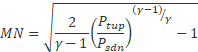
Calculation of Flow Rate and Vena Contracta Mach Number
For Compressible Flow Equation:
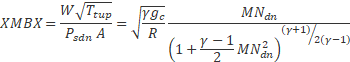
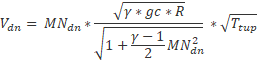
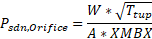
The element flow is then calculated using the equation:
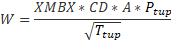
Where XMBX = Total pressure flow parameter
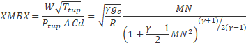
Where
For Incompressible Flow Equation:
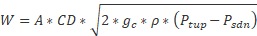
Or
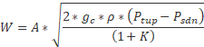

Where CD for different subtype are estimated based on the definition provided in Quick guide of Effective Area Orifice Element.
Note:
Y values →CD, K, Flow Rate, Flow Function, Velocity
X-Values →Pressure Ratio, Delta-P, Reynolds Number, Valve Position, Head, Pressure Parameter, Source Pressure
Linear interpolation is employed between the values in the table to determine Y Values. If X-Value is less than its first value entry in the table, the first Y-Value entry is used. If X-Value is greater than its last value entry in the table, the last Y-Value entry is used. Flow Simulator doesn’t do any extrapolation if the values are outside the prescribed input limits. If CD values greater than 1.0 are included in the table of values, they will be used but the orifice exit area used for the calculation of orifice exit conditions will be increased from A to A*CD. If the range of the table is exceeded or a CD value greater than 1.0 returned on the final iteration, a warning message will be printed.
Calculation of Orifice Exit Conditions
The flow is first expanded from the vena contracta throat to the exit conditions before any effect of heat addition, QIN, is considered. it is assumed that the flow is expanded adiabatically (limited to Mach number = 1.0) to the mechanical area of the orifice at the exit static pressure, . The static pressure exit flow parameter, exit Mach number and adiabatic exit velocity is calculated as:
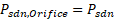
If  , the static pressure at the orifice exit is calculated
as:
, the static pressure at the orifice exit is calculated
as:
Otherwise:
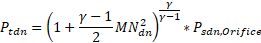
The exit total pressure is then calculated as:
The effect of heat addition specified as QIN is added next, assuming that only the exit temperature and velocity, and not the exit Mach number, are affected. The temperature rise (or drop if QIN is negative) is calculated using an average value of specific heat (Cp)
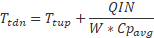
Cpavg: Specific heat at the average of TTS and TEX, pressure PSEX, and secondary fluid mass fraction FS(IC)
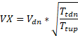
A new exit velocity is next calculated as:
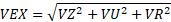
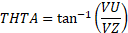
If 0 values are input for each of the exit head loss variables (KEZ, KEU and KER), the element exit velocity, VEX, is set to VX, and the relative radial and tangential flow angles at the exit plane (THTA and PH) are taken to be the values specified for the input variables THTELX and PHIELX respectively. If any of these exit head loss variables are input as non-zero values, the exit velocity components are recomputed as:


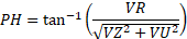
and then the relative exit velocity and flow angles are computed as:
Additional Momentum Loss
For Additional Momentum loss, Portion of Upstream Dynamic Head loss, Exit K Loss refer Solver General theory section.
Effective Area Element Outputs
The following listing provides details about effective area orifice output variables.
| Name | Description | Units |
|---|---|---|
| DQ_IN | Portion of Ustrm Chamb. Dyn. Head Lost (Usually, an echo of the user input unless modified inside Flow Simulator.) |
Flag |
| Axial (K_EXIT_Z) Tangential (K_EXIT_U) Radial (K_EXIT_R) |
Exit K Loss (Usually, an echo of the user input unless modified inside Flow Simulator.) |
Unitless |
| ELEMENT_THETA | Tangential Angle (Usually an echo of the user input but converted to radians.) |
radians |
| ELEMENT_PHI | Radial Angle (Usually an echo of the user input but converted to radians.) |
radians |
| REL_INLET_ANGLE | It is a relative inlet angle calculated based on upstream chamber velocity | Deg |
| ELEMENT_RPM | RPM (Rotor index) (Usually, an echo of the user input unless modified inside Flow Simulator.) |
rad/min |
| RAD | Radius (Usually, an echo of the user input unless modified inside Flow Simulator.) |
in, m |
| ELEMENT_AREA | Cross-sectional area. (Usually, an echo of the user input unless modified inside Flow Simulator.) |
inch2, m2 |
| CD | Discharge coefficient. (Usually an echo of the user input unless modified inside Flow Simulator.) |
(fraction) |
| K | Head loss coefficient. Calculated from the discharge coefficient using equation. |
(unitless) |
| EXIT_AREA | Exit area used for calculating exit conditions of the orifice
element. This output is only printed when an exit area is used
(EXIT_AREA>0). A default value of 0 has no effect on exit
conditions. (Output is an echo of the user input.) |
inch2, m2 |
| PTS | Driving pressure relative to the rotational reference frame (that is, rotor) at the restriction inlet. | psi, mPa |
| PTEX | Total pressure relative to the rotational reference frame (that is, rotor) at the restriction exit including supersonic effects. | psi, mPa |
| PSEX | Static pressure relative to the rotational reference frame (that
is, rotor) at the restriction exit. Limited by critical pressure ratio for supersonic flows. |
psi, mPa |
| PSEB | Effective sink (static) pressure downstream of the restriction. | psi, mPa |
| TTS | Total temperature of fluid relative to the rotational reference frame (that is, rotor) at the restriction inlet. | deg F, K |
| VCMN | Fluid Mach number relative to the rotational reference frame (that is, rotor) at the vena contracta. | (unitless) |
| VXA | Fluid velocity relative to the rotational reference frame (that is, rotor) at the restriction exit before heat input (QIN) effects. | ft/s, m/s |
| EXMN | Fluid Mach number relative to the rotational reference frame (that is, rotor) at the restriction exit before heat input (QIN) effects. | (unitless) |
| QIN | Heat input. Positive values indicate heat added to the fluid; negative values indicate heat removed. |
BTU/s, W |
| DT | Change in total temperature relative to the rotational reference frame (that is, rotor) due to heat input (QIN). | deg F, K |
| TEX | Total temperature relative to the rotational reference frame (that is, rotor) at the restriction exit. | deg F, K |
| VEX | Fluid velocity relative to the rotational reference frame (that is, rotor) at the restriction exit including heat input (QIN) effects. | ft/s, m/s |
| VABS | Magnitude of the fluid total absolute velocity. | ft/s, m/s |
| VTAN_ABS | Magnitude of the fluid absolute tangential velocity. | ft/s, m/s |
| VAXIAL | Magnitude of the fluid axial velocity. | ft/s, m/s |
| VRAD | Magnitude of the fluid radial velocity. | ft/s, m/s |
| THTA_ABS | Fluid absolute tangential flow angle. | rad |
| VREL | Magnitude of the fluid total velocity relative to the element. | ft/s, m/s |
| VTAN_REF | Reference frame tangential velocity. | ft/s, m/s |
| VTAN_REL | Magnitude of the fluid tangential velocity relative to the element. | ft/s, m/s |
| VNORM | Magnitude of the fluid total velocity relative to the element. | ft/s, m/s |
| THTA_REL | Fluid relative tangential flow angle. | rad |
| TTABS | Absolute total temperature. | deg F, K |
| TTREL | Relative total temperature. | deg F, K |