Cavities
Cavity Description
The rotating cavity solver is used to calculate the fluid rotational velocity and temperature change in control volumes bounded by rotating (and stationary) surfaces. Cavities are commonly needed to model the secondary flows (flow not in the main gas path) of turbo machinery applications. The solver uses an angular momentum balance between the flow entering and leaving the control volume and the torque applied to the flow by the rotating and stationary surfaces. The rotating fluid leads to a pressure gradient in the radial direction. The rotating velocity (swirl) of the fluid is used by the vortex elements to introduce the pressure gradient into the flow model. The temperature change due to the cavity is automatically applied to the flow.
Quick Guide for Creating a Cavity in the GUI
- Right-click on a vortex chamber or inertial chamber (a cavity cannot be
applied to a plenum or momentum chamber) and select Create
Cavity. An optional cavity title can be given to help
identify it.
Figure 1. 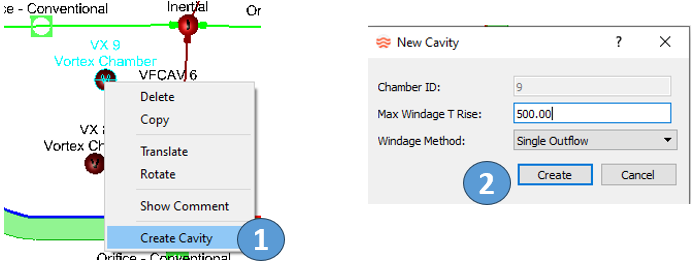
- Create the surfaces of the cavity. Cavities usually have multiple surfaces, with each surface associated with a different part in the machine. Each surface must have a unique speed so do not use points from a rotating and stationary part on the same cavity surface. Cavity surface points can be created using 1)the traditional approach of selecting a point on the screen close to the CAD geometry or 2) using the CAD geometry to place points directly on the curves.
- The Create option works best for creating a new
surface with the traditional approach. Use the
Insert, Move, and
Delete options to edit an existing surface.
Select the surface points on the screen to fully define the cavity
surface.
Figure 2. 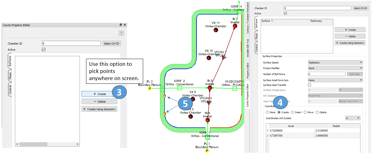
- Create surface points directly on the CAD geometry one at a time.
Figure 3. 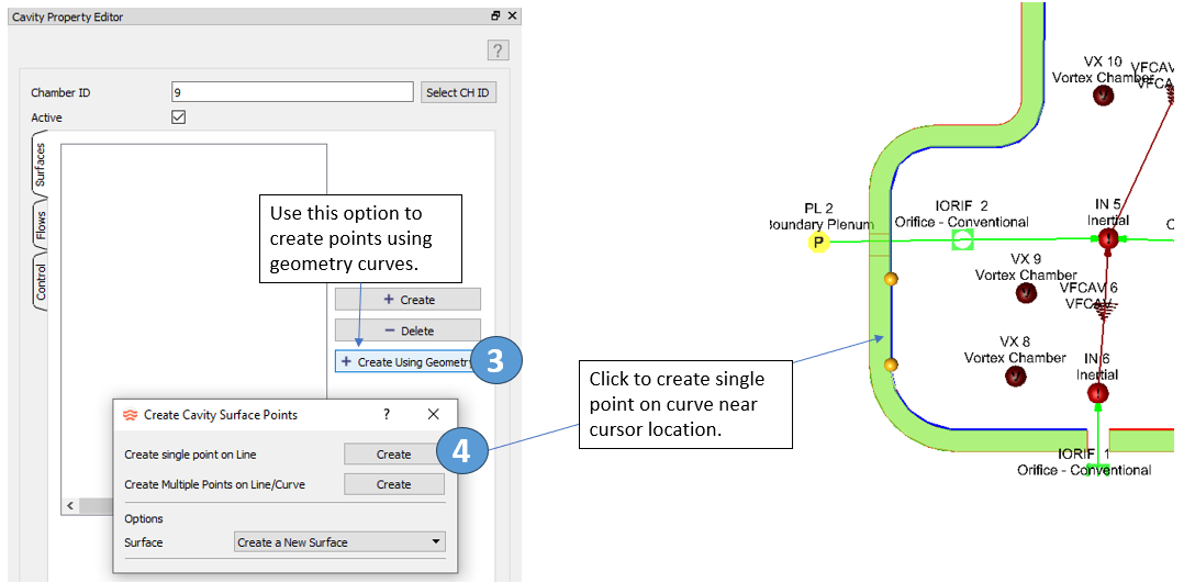
- Create multiple surface points directly on the CAD geometry with one
click.
Figure 4. 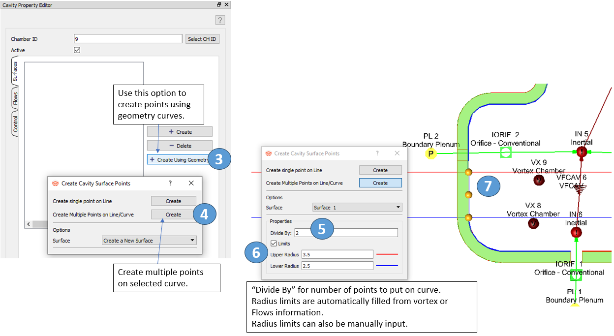
- You can modify the friction options for the surface if needed. Bolt rows or other features that affect the surface drag can be included.
- After the surfaces are created, the flows entering and exiting the control
volume must be defined. The Auto Fill button can be
used to populate the table. However, “Auto Fill” must have information from
completed elements to work properly, so complete input for elements that are
attached to the cavity chamber before attempting “Auto Fill”. Manual edits
to this table may be required. The three inputs for each flow include:
- Radius: The radius (inches) of the flow entering or exiting the cavity control volume.
- Swirl Source: The chamber containing the swirl of the flow entering the cavity. Enter a “0” if the swirl of the fluid exiting the Flow Element is to be used (needed if no chamber contains the proper swirl). The Swirl Source for Outflows will only be used by the solver if the flow reverses in the element.
- Flow Element: The number of the flow entering or exiting the cavity control volume.
Figure 5. 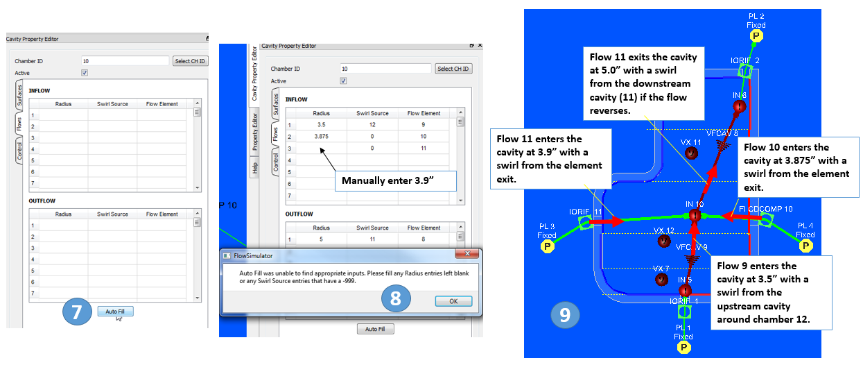
- Use the Cavity section in the Flow Model Browser to
adjust the cavity display and to delete cavities if needed. The
Colour by surface rotor speed is useful for
visualizing the surface speeds (Blue = stationary and Red = Rotor 1).
Left-click twice on a cavity in the list to center the view on the cavity.
The User Settings panel has the surface point size
control as a percentage of the chamber/element symbol size.
Figure 6. 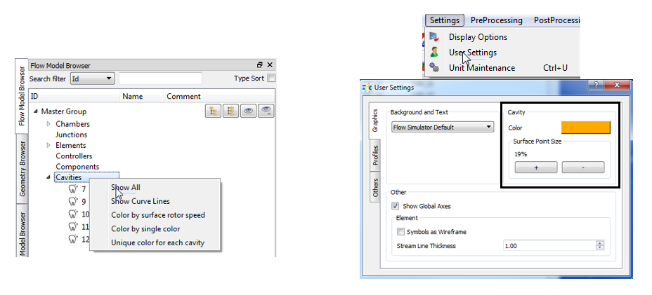
Cavity Inputs
The Flow Simulator cavity solver input data consists of four separate name list blocks near the bottom of the model database file. The first of these, $CAV1, defines the number of separate cavities to be analysed and is used to set any global input variables that are related to cavities. Each cavity requires a $CAV name list block and a $FLOWCAV name list block. Both $CAV and $FLOWCAV define cavity variables with the $FLOWCAV variables providing information about flow, swirl, pressure, and temperature connectivity between the cavity and chambers in the model. Each $CAV name list block contains NSURF, which identifies the number of surfaces in the cavity or sub-cavity. NSURF is the number of sets of $SURF name list blocks that are required for the cavity or sub-cavity since the $SURF name list block provides details about cavities surfaces. The following listing contains a description of the cavity inputs for each of the name list blocks. All required name list variables have been highlighted.
| Namelist | Variable | Description |
|---|---|---|
| $CAV1 | Cavity Solution Tolerance (TOLCV) |
Cavity solution tolerance for net wall torque / angular momentum
change. (Default value = 1.0E-04) |
| $CAV1 | Max Cavity Interval (MAX_CAV_INTERVAL) |
Maximum number of Flow
Simulator solver iterations between cavity solver
runs. If the limit is reach, the cavity solver is forced to
run. (Default value = 50) |
| $CAV1 | Max Global Cavity Run (MAX_FLOBAL_CAV_RUN) |
Maximum number of times cavity will run after flow balance is
achieved before giving up. (Default value = 10) |
| $CAV1 | Max Cavity Runs (MAX_CAVITY_RUNS) |
Maximum number of cavity solver runs. (Default value = 99999) |
| $CAV1 | Cavity First Run Iteration
Limit (CAV_FIRST_RUN_ITER_LIMIT) |
Number of iterations at the start when CAV_FIRST_RUN_ERR_LIMIT
applies. (Default value = 50) |
| $CAV1 | Cavity First Run Error
Limit (CAV_FIRST_RUN_ERR_LIMIT) |
Maximum flow balance error to trigger a cavity run. Used when number of Flow Simulator iterations is less than or equal to CAV_FIRST_RUN_ITER_LIMIT. (Default value = 100%) |
| $CAV1 | Cavity Run Sec. Limit
Factor (CAV_RUN_SEC_LIMIT_FACTOR) |
Maximum flow balance error to trigger a cavity run. Used when the number of Flow Simulator iterations is greater than CAV_FIRST_RUN_ITER_LIMIT. (Default value = 2.5%) |
| $CAV1 | Swirl Change Tolerance (XK_CHANGE_TOL) |
Tolerance for swirl change between cavity runs. If swirl change is greater than XK_CHANGE_TOL, then Flow Simulator will continue running. (Default value = 0.02) |
| $CAV1 | Global Cavity Run Limit (FLOBAL_CAV_RUN_LIMIT) |
Value of maximum error (cavity chamber flow balance) allowed
above which the individual cavity is not run. (Default value = 50.0%) |
| $CAV1 | Torque Integration Method (TRQINTG) |
Cavity torque integration method. (Default value = 1) |
| $CAV1 | Max Iterations (MAX_ITER) |
Maximum number of iterations for cavity solver
convergence. (Default value = 200) |
| $CAV1 | Cavity Surface Tolerance (SURTOL) |
Tolerance value to define a surface segment as either horizontal
or vertical (in). (Default value = 0.0012) |
| $CAV1 | SURFTREAT | Cavity surface treatment flag. Method used to determine if a
surface segment is cylindrical or conical/vertical. This flag is not available in or written by the GUI. Internally, Flow Simulator interprets this flag based on the value of TRQINTG as shown below. |
| $CAV1 | CF_DISK_ROTOR CF_DISK_STATR CF_CYLR_ROTOR CF_CYLR_STATR |
The global cavity surface friction option.
These options are used on all cavity surfaces that do not have a
local cavity surface friction option specified. -1: User Specified Friction Factor 0: Use default friction correlations 5: Disk Friction Factor from Dasoghe reference 11: Disk Friction Factor from Sultanian reference 12: Cylinder Friction Factor from Sultanian reference >1000: Custom friction factor correlation |
| Namelist | Variable | Description |
|---|---|---|
| $CAV | NSURF | Number of cavity surfaces. (Mandatory Input) |
| $CAV | Title (TITLE) | Title for cavity, which can contain up to 70 characters. |
| $CAV | CH (NCHAMB) |
Chamber identification number of the chamber that stores the
swirl factor and rotor index used by this cavity. NCHAMB serves as the cavity identifier (Mandatory Input) |
| $CAV | ACTIVE_CAV [checkbox] |
Flag that indicates whether or not this cavity should be solved.
Can be turned on/off using the checkbox in the Flow Simulator cavity window. If ACTIVE_CAV is 0, this is equivalent to removing the cavity from the model. (Default value = 1) |
| $CAV | ICSOL | Cavity windage calculation method. 0: Single outflow method: windage computed for rotor drag. 1: Multiple outflow method: windage computed for stator drag and pumping. (Default value = 1 = MULTIPLE_OUT) |
| $CAV | DTLIM | Maximum temperature rise (F) due to windage. (Default value = 500 F) |
| $CAV | CF_DISK_ROTOR CF_DISK_STATR CF_CYLR_ROTOR CF_CYLR_STATR |
The local cavity surface friction option. These options are used for the current cavity surfaces. If set to 0, the global options are used. |
| $SURF | Surface Speed (IXN) |
Surface rotation pointer (to ELERPM array from general data). A
value of 0 indicates the surface is stationary. (Mandatory Input) |
| $SURF | X | Axial position (Mandatory Input) |
| $SURF | R | Radial position (Mandatory Input) |
| $SURF | Number of Bolt Rows (NBROW) |
Number of bolt rows. (Default value = 0) |
| $SURF | Number of bolts (NB) |
Number of bolts for each row. (Used only when NBROW > 0) |
| $SURF | Bolt circle radius (RB) |
Bolt circle radius (in) for each bolt row. (Used only when NBROW > 0) |
| $SURF | Bolt diameter (DB) |
Bolt diameter (in) for each bolt row. (Used only when NBROW > 0) |
| $SURF | Bolt height (HB) |
Bolt height (in) above surface for each bolt row. (Used only when NBROW > 0) |
| $SURF | Bolt drag coefficient (CDB) |
CD for each bolt row (spacing correction is automatic). (Used only when NBROW > 0) |
| $SURF | Surface Roughness (CDO1) |
CD flag for hooks or H/C multipliers, etc. 0: Smooth wall (no multiplier of additional roughness) > 0: Horner shape factor < 0: Surface multiplier (program uses absolute value) (Default value = 0.) |
| $SURF | Protrusion Pitch (XP1) |
Distance (in) between protrusions. (Only used if CDO1 > 0.) |
| $SURF | Protrusion Height (H1) |
Height (in) of protrusion. (Only used if CDO1 > 0.) |
| $SURF | FR1 | User supplied friction factor to be used instead of the calculated value. |
| $SURF | FORCE_DIR | The axial direction of the pressure force on this cavity surface.
The pressure force and force direction will be used during post
processing to sum axial forces on cavity surfaces. -1: pressure force acts in negative axial direction 0: no pressure force for this surface 1: pressure force acts in positive axial direction |
| $SURF | HT | Heat Transfer option for this surface 0: no heat transfer on this surface 1: apply heat transfer to this surface |
| $SURF | TSURF | The cavity surface temperature for heat transfer. (deg F) |
| $SURF | HTC_REL | The Heat Transfer Coefficient relation. -1: Constant HTC >1000: Use a custom HTC correlation, ROTATING_CAVITY_NU custom subtype. |
| $SURF | HTC | The Heat Transfer Coefficient when HTC_REL=-1, BTU/(hr ft^2 F) |
| $FLOWCAV | CH Pressure ID (P) |
Chamber identification number where cavity pressure is stored and
retrieved. If left unset, Flow Simulator
will use NCHAMB. (Default value = cavity NCHAMB) |
| $FLOWCAV | CH Temp. ID (TIN) |
Chamber identification number where cavity temperature is stored
and retrieved. If left unset, Flow Simulator will use NCHAMB. (Default value = cavity NCHAMB) |
| $FLOWCAV | FS | Secondary fluid mass fraction of entering flow or pointer to
Flow Simulator chamber or element
(optional). (Default value = cavity NCHAMB) |
| $FLOWCAV | RIN1 | Radius (in) to flows entering the cavity from the engine
centerline. (One value required for each WIN.) (Mandatory Input) |
| $FLOWCAV | ROUT1 | Radius (in) to flows leaving the cavity from the engine
centerline. (One value required for each WOUT.) (Mandatory Input) |
| $FLOWCAV | XNW | Source of swirl for flows entering the cavity. CHNUM: Use swirl from chamber CHNUM. 0: Use swirl from the element exit. (There must be an XNW entry for each WIN and WOUT entry in case flow reverses. The entries that correspond to WOUT are used when flow reverses.) (Mandatory Input) |
| $FLOWCAV | WIN | Element identification number of elements that are expected to
have flows entering the cavity. (Mandatory Input) |
| $FLOWCAV | WOUT | Element identification number of elements that are expected to
have flows leaving the cavity. (Mandatory Input) |
Cavity Theory Manual
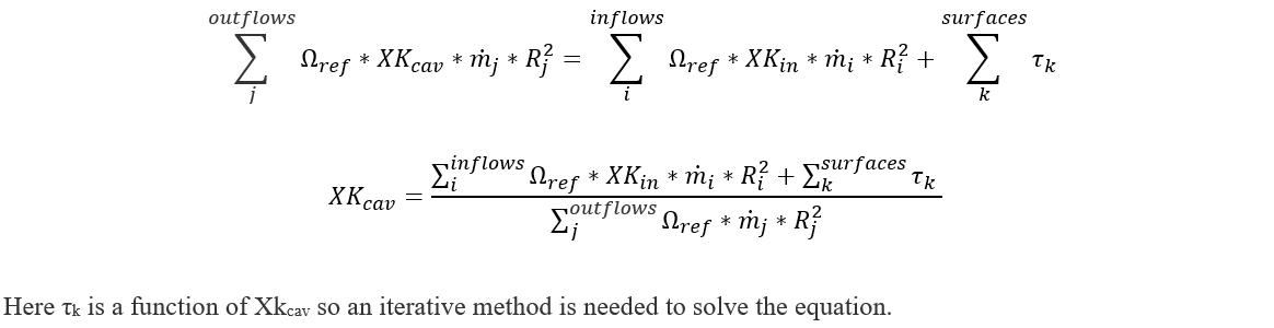
The fluid rotational speed in the cavity is computed based on inlet velocities, mass flows, and computed surface torque. The surface torque and cavity swirl factor are interdependent. The cavity solver carries out an iterative procedure to ensure both sets of equations are satisfied. In particular, the Regula Falsi method is employed with the initial guess for cavity swirl to iteratively seek the correct cavity swirl value that satisfies the angular momentum equation within the specified tolerance. For the first call to the cavity solver, the initial guess is based on the user’s entry from upstream chamber swirl (or downstream chamber swirl if flows are reversed). For subsequent cavity runs, the initial guess is based on the previous cavity analysis result. The calculated cavity swirl is representative of the cavity fluid control volume and is used as the cavity exit swirl.
In Flow Simulator, vortices and cavities follow the chamber-centric modelling approach. Cavities can be modelled with multiple inflows and outflows. This section presents the physical equations that govern the cavity vortex as implemented in Flow Simulator. The feature that distinguishes the cavity vortex from free and forced vortexes is its calculation of torque caused by the rotating metal parts acting on the fluid passing through the cavity. Torque affects fluid velocity, temperature, and pressure in the cavity, which are subsequently calculated by including the torque term in the momentum and energy balance equations.
The Angular Momentum equation
Nomenclature:
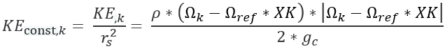
KE: Volumetric Kinetic Energy
ρ: Fluid density
r, R: Radius from the engine centreline
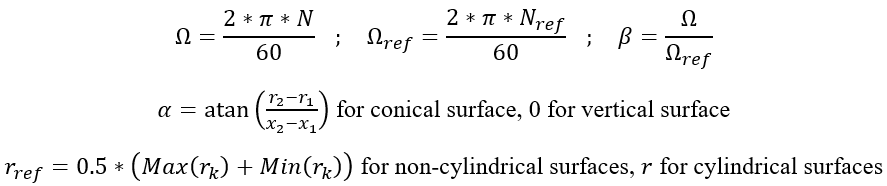
Ω: Rotational speed
N: Speed in terms Rotation per Minute
XK: Ratio of the fluid absolute rotational speed to the rotational reference frame (i.e. rotor)
τ: Torque
cf: Coefficient of friction
x: Axial location of surface segment endpoint
α: Angle that the surface makes with the engine centreline
Nb: Number of bolts in the bolt row
Cdb: Cd for the bolt row (spacing correction is automatic)
Sb: Bolt interference scale factor for the bolt row
Ab: Cross sectional area of exposed bolt head surface
Rb: Radius from the engine centerline the bolt row
k: Cavity surface index
csf: Cylindrical surface skin friction
nsf: Non-cylindrical surface skin friction
CAV: Cavity control volume
ref: Cavity rotational reference frame
s: Cavity surface segment index
1,2: Cavity surface segment endpoints
i, j: Cavity inflow/outflow element indexes
const: Indicates that any radius terms have been removed from the parameter, this is useful to allow parameters to be pulled outside of an integral taken with respect to radius as “constants”
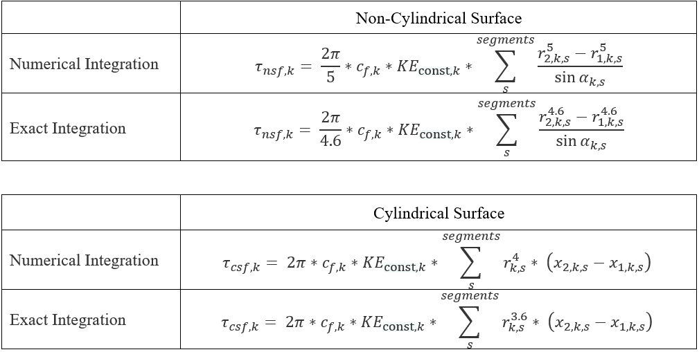
Surface Skin Friction Torque:
Torque due to non-cylindrical surfaces (Conical, Vertical surfaces with respect to engine centreline) and Cylindrical surfaces (Horizontal surfaces with respect to engine centreline) is computed either by a numerical integral or by the exact integral method. The torque integration method option is available under SolveràAnalysis SetupàSolver ConvergenceàCavity Solver Tolerancesà Torque integration method dropdown menu. The torque coefficients equations are summarized under following table:
The Volumetric kinetic energy term is defined as
Surface Bolts Form Drag Torque
Torque equation for bolts can be found in Sultanian (ref 6), section 4.3.2.
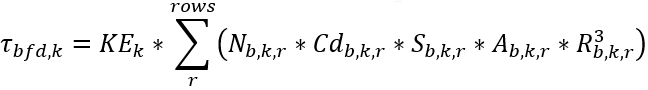
The interference scale factor, Sb,k,r is based on Fig 30 on page 5-14 of Hoerner (ref 7).
The skin friction coefficient equation depends on whether the surface is stationary or rotating. The following table presents the skin friction coefficient equations
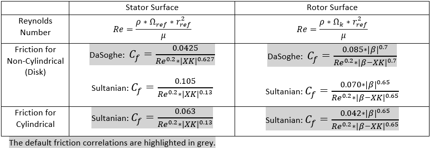
The relation for friction coefficients on non-cylindrical surfaces that is used in all the cavity solvers was developed from data for rotating disks. Since most of the non-cylindrical surfaces in the cavities of interest are annuli rather than complete disks, use of an average radius was selected as the preferable method for the Flow Simulator cavity solver. As verified by running a wide range of test cases, the variation in results due to these methodological differences are generally minor and well within the range of engineering accuracy for the analysis.
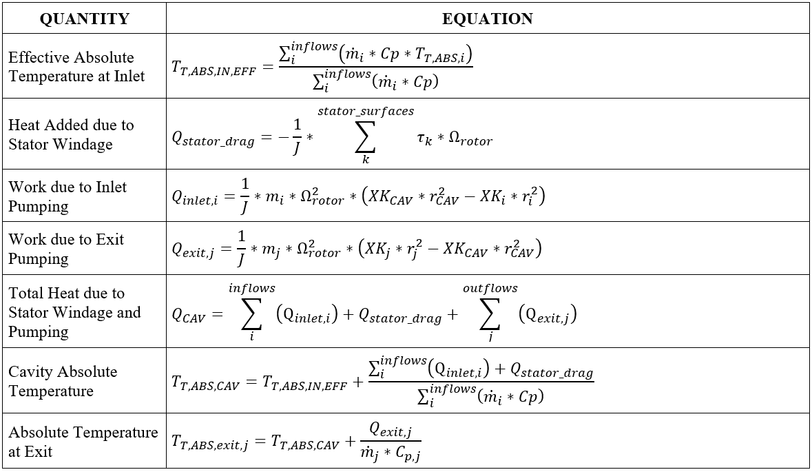
Delta Temperature across cavity:
The temperature rise across the cavity is calculated using energy balance accounting for the windage generated by rotor. The Energy balance and Delta Temperature Rise calculation are as follows:
Single In/Outflow Cavity:
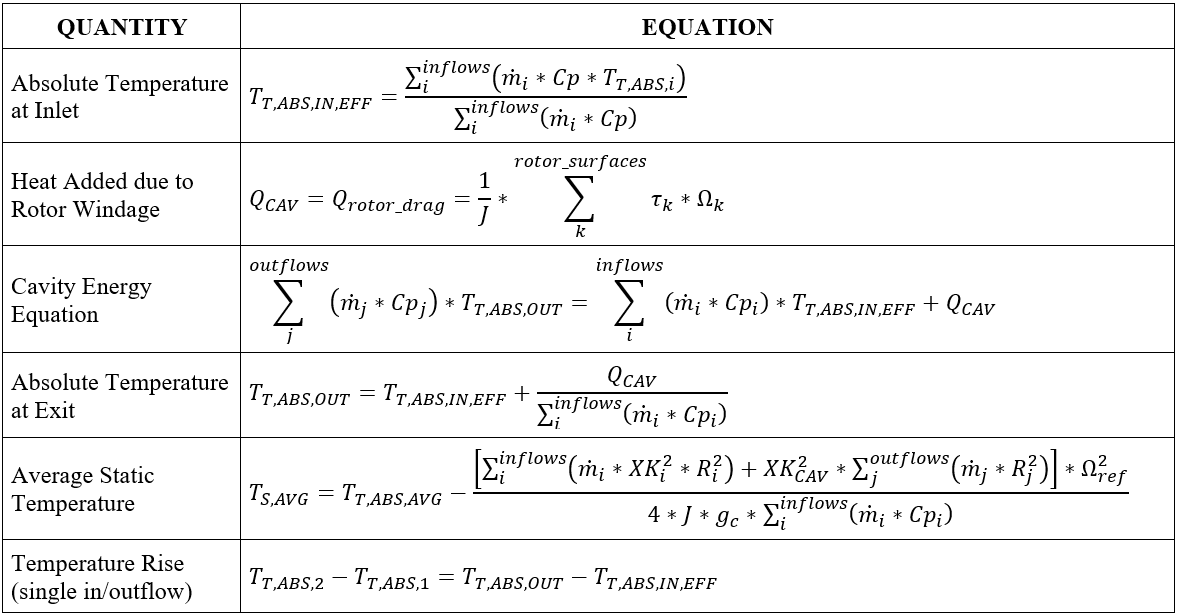
Multiple In/Outflow Cavity
Cavity Heat Transfer
In addition to the fluid temperature change due to windage, the fluid temperature can also change due to the fluid convection to the cavity surface. The typical convection heat transfer equation is used:
HTC = Heat transfer coefficient (user-supplied) or calculated by the correlation.
Area = Surface area
Tsurf = The surface temperature (user-supplied).
Tfluid rel = The relative fluid total temperature, adjusted for fluid and surface rotation.
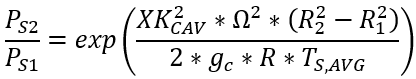
Cavity Pressure
The cavity pressure is simply the pressure that Flow Simulator has assigned to the cavity chamber. If the cavity chamber is an inertial chamber the pressure is calculated during the normal network solution process. If the cavity chamber is a vortex chamber, the pressure comes from the vortex element segment that uses this vortex chamber. The pressure is only used in the cavity solver to determine the fluid properties. The pressure ratio across a cavity can only be calculated using a vortex element.
Cavity Surface Axial Force
The cavity surface axial force is calculated as:
Forcedir=Force direction (user-supplied) for this surface, either -1 or 1.
Pchamber=Static pressure of the cavity chamber.
Area = Surface area for this cavity surface, .
Radius1 = Radius of first point of cavity surface.
Radiusn = Radius of the last point of the cavity surface.
The cavity forces are summed for all cavities using the surface rotation and written to the *.cav.out file. For example, all forces are summed for the surface rotating with rotor 1 RPM.
Cavity Outputs
The following listing provides details about cavity output variables. The first table shows the cavity output variables in the summary section. The second table shows the cavity output variables in the detailed (individual) cavity results.
| NAME | DESCRIPTION | UNITS ENG, SI |
|---|---|---|
| NCHAMB | Cavity identification number, also the number of the associated chamber. | (ID) |
| XK | Ratio of the absolute rotational speed of the fluid to the reference frame rotational speed (REF_RPM). | (unitless) |
| WINDAGE | Heat added due to cavity windage. For the new multiple outflow cavity methodology, this is the sum of the stator windage and rotor pumping for element flow(s) exiting the cavity. |
BTU/s, W |
| DT_WNDG | Total absolute temperature rise due to windage. For the new multiple outflow cavity methodology, this is the sum of the stator windage and rotor pumping for element flow(s) exiting the cavity. |
deg F, K |
| TEMPERATURE | Total absolute temperature in the cavity, also stored as TTC
of cavity chamber (NCHAMB). For the new multiple outflow cavity methodology, this temperature only includes the effect from the stator windage and rotor pumping for all element flows entering the cavity. The change in temperature due to rotor pumping for any flow(s) exiting the cavity is applied to the chamber(s) downstream of the element(s). |
deg F, K |
| PRESSURE | Static pressure in the cavity, also stored as PSC of cavity chamber (NCHAMB). | Psia, mPa |
| FL2_MASS_FRAC | Secondary fluid mass fraction, also stored as FS of the cavity chamber (NCHAMB). | (unitless) |
| CONV_ITER | Number of iterations required for the cavity to converge on the most recently completed cavity run. | (number) |
| REF_RPM | Reference rotational speed for the cavity. Used with swirl factor (XK) to calculate fluid rotational speed |
rev/min |
| NAME | DESCRIPTION | UNITS ENG, SI |
|---|---|---|
| CAVITY CHAMBER | Cavity identification number, also the number of the associated chamber. | (ID) |
| CAVITY SOLVER ITERATIONS |
Number of iterations required for the cavity to converge on the most recently completed cavity run. | (number) |
| REF RPM | Reference rotational speed for the cavity. Used with swirl factor (XK) to calculate fluid rotational speed |
rev/min |
| CAVITY XK | Ratio of the absolute rotational speed of the fluid to the reference frame rotational speed (REF RPM). | (unitless) |
| CAVITY FLUID RPM | Rotational speed of the fluid in the cavity | rev/min |
| CHAMBER TEMPERATURE | Total absolute temperature in the cavity, also stored as TTC
of cavity chamber. For the new multiple outflow cavity methodology, this temperature only includes the effect from the stator windage and rotor pumping for all element flows entering the cavity. The change in temperature due to rotor pumping for any flow(s) exiting the cavity is applied to the chamber(s) downstream of the element(s). |
deg F, K |
| CONVERGENCE STATUS |
Cavity convergence status | (flag) |
| CAVITY WINDAGE METHOD |
Cavity windage calculation method TOTAL APPLIED TO CAVITY All cavity results are applied to the cavity chamber. This is used for single outflow cavities (ICSOL = 0). MULTIPLE OUTFLOW, PUMPING APPLIED TO FLOW Stator windage and rotor pumping for flow(s) entering the cavity are applied to the cavity chamber. Rotor pumping for flow(s) exiting the cavity is applied to the chamber(s) downstream of the element(s). This is used for multiple outflow cavities (ICSOL = 1). |
(flag) |
| ROTOR_WINDAGE (STATOR + PUMP WINDAGE) |
Heat added in the cavity due to windage (friction and drag) and rotor pumping of the fluid. | BTU/s, W |
| T RISE FROM ROTOR WINDAGE (T RISE FROM STATOR + PUMP WINDAGE) |
Temperature rise due to cavity windage and rotor pumping. | deg F, K |
| SECOND FLUID MASS FRACTION |
Secondary fluid mass fraction, also stored as FS of the cavity chamber (NCHAMB). | (unitless) |
| PRESSURE | Static pressure in the cavity, also stored as PSC of cavity chamber (NCHAMB). | psia, mPa |
| SURFACE | Cavity surface index. | (index) |
| SURFACE_RPM | Rotational speed of each cavity surface | rev/min |
| TOTAL_TORQUE | Total torque applied to the fluid by each surface. | ft*lbf, N-m |
| GEOM_PARAM | An intermediate variable that gathers geometric data for cylindrical segments and non-cylindrical segments of each surface and is then used to compute surface torque. | ft5, m5 |
| RADIUS | Effective radius of each cavity surface. | inch, m |
| COEFF_FRIC | Effective skin friction coefficient of each surface. | (unitless) |
| RE | Fluid Reynolds number for each surface. | inch, m |
| SURF_WINDAGE_Q | Windage due to each surface. | BTU/s, W |
| SURF_WINDAGE_DT | Temperature rise due to windage from each surface. | deg F, K |
| ELEMENT | Element identification number for each cavity inflow and outflow. | (ID) |
| ANG_MOM | Angular momentum due to each flow into and out of the cavity. | ft*lbf, N-m |
| FLOW | Flow rate of each cavity inflow and outflow. | lbm/s, kg/s |
| XK_SRC | Source of fluid swirl factor for each cavity inflow. CH: Fluid swirl factor for the flow is obtained from specified chamber. EL: Fluid swirl factor for the flow is obtained from specified element. |
(ID) |
| XKIN | Swirl factor of each cavity inflow. | (unitless) |
| RPM_REF | Reference rotational speed for each cavity inflow. Used with swirl factor (XK) to calculate fluid rotational speed |
rev/min |
| PUMP_Q | Rotor pumping (heat) for each flow into and out of the
cavity. Only printed when using MULTIPLE OUTFLOW, PUMPING APPLIED TO FLOW (ICSOL = 1) cavity method. |
BTU/s, W |
| PUMP_DT | Change in fluid temperature due to rotor pumping for each
flow into and out of the cavity. Only printed when using MULTIPLE OUTFLOW, PUMPING APPLIED TO FLOW (ICSOL = 1) cavity method. |
deg F, K |
| PUMP_CH | Identification number of the chamber to which the rotor
pumping (heat) is applied to for each flow into and out of the
cavity. For flow(s) into the cavity, the heat is applied to the cavity chamber. For flow(s) exiting the cavity, the heat is applied to the chamber(s) downstream of the element(s). Only printed when using MULTIPLE OUTFLOW, PUMPING APPLIED TO FLOW (ICSOL = 1) cavity method. |
(ID) |
References
- Da Soghe, R., Facchini, B., Innocenti L. and Micio, M., Analysis of Gas Turbine Rotating Cavities by a One-Dimensional Model: Definition of New Disk Friction Coefficient Correlations Set, ASME Journal of Turbomachinery, Vol 133, 2011.
- Da Soghe, R., Innocenti L., Andreini A., and Poncet, S., Numerical benchmark of turbulence modeling in gas turbine rotor-stator system, ASME Turbo Expo 2010, GT2010-22627, 2010.
- Da Soghe, R., Facchini, B., Innocenti L. and Micio, M., Some Improvements in a Gas Turbine Stator-Rotor Systems Core-Swirl Ratio Correlation, International Journal of Rotating Machinery, Volume 2012, Article ID 853767, 2012.
- Owen, J.M. and Pincombe, J.R., Velocity measurements inside a rotating cylindrical cavity with a radial outflow of fluid, Journal of Fluid Mechanics, Vol. 99(1), pages 111 – 127, 1980.
- Owen, J.M., Pincombe, J.R. and Rogers R. H., Source-sink flow inside a rotating cylindrical cavity, Journal of Fluid Mechanics, Vol. 155(1), pages 233 – 265, 1985.
- Bijay K. Sultanian, “Gas Turbines – Internal Flow Systems Modeling”, Cambridge Aerospace series, 2018, ISBN 978-1-107-17009-4
- Hoerner, S. F., “Fluid-Dynamic Drag”, 1965, Author-Published