Valve Elements
Valve Element General Description
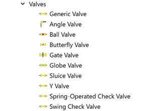
Flow Simulator has a range of control valves that can be used in Flow Network Modeling. They include:
- Generic Valve: This type of valve element is used to model valve types that are not supported directly.
- Angle Valve: Valve with its outlet opening oriented at right angles to its inlet opening.
- Ball-Valve: This valve type is form of quarter-turn valve which uses a hollow, perforated and pivoting ball to control flow through it
- Butterfly valve: Type of quarter turn valve. A quarter turn valve can open or close whenever the handle is turned 90 degrees (a quarter of a turn).
- Gate Valve: They are opened by lifting a barrier (gate) out of the path of the fluid.
- Globe Valve: These valve elements restrict the flow of fluid by altering the distance between a movable plug and a stationary seat.
- Sluice Valve: This valve element is operating like gate valves, a sluice valve operates in the either fully on or fully off position and is used to allow or stop, but not regulate, flow.
- Y Valve: This type of valve element can be used when the fluid flow required to be conveniently diverted. They are easily mounted to a bulkhead. The valves are operated by a simple 120° movement.
- Spring Operated Check Valve: these valve elements function in the same way as swing check valves, but they have a spring to stay closed when there is no flow in the correct direction. That means that as soon as fluid stops flowing through, the valve claps shut.
- Swing Check valve: A swing check valve is mounted with a disc that swings on a hinge or shaft. The disc swings off the seat to allow forward flow and when the flow is stopped, the disc swings back onto the seat to block reverse flow.
Quick Guide for Valve Element Model Creation in the GUI
All valve elements can be found under “Compressible Gas Elements” and “Incompressible Liquid Elements” – “Valves” section.
The geometric inputs, valve position, momentum losses and compressible gas corrections (if the flow equation type is compressible gas) are mandatory inputs. And inputs related to heat, additional momentum losses, rotation effects, and valve characteristics are required if these effects are desired to be included in the element calculations. Descriptions about each input is described below in “Valve Elements Inputs” section. The (valve) position is synonymous with 'Valve Opening' and should be specified in Percentage (0% = closed, 100% = fully open). The variation of valve loss coefficient with position is specified as a curve. The valve position is fixed for a Steady State simulation, unless some form of feedback controller is used. In that case valve position will be adjusted, dependent upon some other parameter in the network.
Valve Element Input Variables
Valve Element inputs.
| Valve Element Input Variables | ||
|---|---|---|
| Index | UI Name (.flo label) | Description |
| 1 | Valve Type (VALVE_TYPE) | The following Valve types are available. 0: Generic Valve (used to model valve types that are not supported directly) 1: Angle Valve 2: Ball Valve 3: Butterfly Valve 4: Gate Valve 5: Globe Valve 6: Sluice Valve 7: Y-Valve 8: Spring-Operated Check Valve 9: Swing Check Valve |
| 2 | Loss Curve ID (LOSS_CURVE) | The following Valve types are available. -1: User-Defined Loss Curve in Table #1 0: Auto-select best loss curve based on VALVE_TYPE 11: Angle Valve K Curve from D.S. Miller’s Internal Flow Systems 2nd Ed. Fig. 14.24 21: Ball Valve K Curve from D.S. Miller’s Internal Flow Systems 2nd Ed. Fig. 14.24 31: Butterfly Valve K Curve A from D.S. Miller’s Internal Flow Systems 2nd Ed. Fig. 14.19 32: Butterfly Valve K Curve B from D.S. Miller’s Internal Flow Systems 2nd Ed. Fig. 14.19 33: Butterfly Valve K Curve C from D.S. Miller’s Internal Flow Systems 2nd Ed. Fig. 14.19 41: Gate Valve K Curve from D.S. Miller’s Internal Flow Systems 2nd Ed. Fig. 14.22 51: Globe Valve K Curve from D.S. Miller’s Internal Flow Systems 2nd Ed. Fig. 14.24 61: Sluice Valve K Curve from D.S. Miller’s Internal Flow Systems 2nd Ed. Fig. 14.22 71: Y-Valve K Curve from D.S. Miller’s Internal Flow Systems 2nd Ed. Fig. 14.24 |
| 3 | Type of Loss Coefficient (LOSS_MODE) | Seven of loss coefficient input curve are supported: 0: Reverse Loss same with Forward Loss 1: Cv (Valve Flow Coefficient) 2: Av (Valve Area Coefficient) 3: Aeff (Effective Area) 4: Cd (Discharge Coefficient) 5: K (K-Loss) 6: Cg (Flow Factor) |
| 4 | Type of Compressible Gas Choking Correction Factor (GASFAC_MODE) | Three types of compressible gas choking correction factor are
supported: 0: Off 1: C1 (Gas Flow Factor) 2: XT (XT Factor) 3: Cf (Critical Flow Factor) equivalent to FL in ISA nomenclature |
| 5 | Cross-section dimension input method (CS_MODE) | The following Cross-section dimension (area, diameter) input
options are available in the valve element: 1: Circular with Area Specified 2: Circular with Diameter Specified (default) 3: Arbitrary Shape (needs Area and Hyd.Diam. input) |
| 6 | Pipe Cross-Section Area (AREA) | Cross-section area of both the pipe and the valve |
| 7 | Pipe Diameter (DIAMETER) | Diameter of both the pipe and the valve |
| 8 | Special Valve Characteristic (VALVE_CHAR) | The following Special Valve Characteristics are available. Any
Special Valve Characteristic can be used in conjunction with any
Valve Type. 0: Standard Reversible Valve 1: Check Valve 2: Pressure Relief Valve |
| 9 | Compressible Gas Correction Factor Curve (GASFAC_CURVE) | -1: User-Defined Gas Factor Curve in Table #2 0: Auto-select best gas factor curve based on VALVE_TYPE 11: Angle Valve C1 Curve from D.S. Miller’s Internal Flow Systems 2nd Ed. Fig. 7.20 21: Ball Valve C1 Curve from D.S. Miller’s Internal Flow Systems 2nd Ed. Fig. 7.20 31: Butterfly Valve C1 Curve (High) from D.S. Miller’s Internal Flow Systems 2nd Ed. Fig. 7.20 32: Butterfly Valve C1 Curve (Low) from D.S. Miller’s Internal Flow Systems 2nd Ed. Fig. 7.20 33: Butterfly Valve C1 Curve (Averaged) from D.S. Miller’s Internal Flow Systems 2nd Ed. Fig. 7.20 51: Globe Valve C1 Curve from D.S. Miller’s Internal Flow Systems 2nd Ed. Fig. 7.20 |
| 10 | Valve Position (VALVEPOS) | Valve Position, All the built-in valve curves used % opening. |
| 11 | Portion of Ustrm Chamb. Dyn. Head Lost (DQ_IN) | Inlet dynamic head loss. Refer General solver theory sections for more details about this input |
| 12 | Rotor Index (RPMSEL) | Reference rotor index for user-supplied swirl. Stationary (Database Value = 0.0) Rotor 1 (Database Value = 1.0): Points to general data Shaft 1 Rotor Speed. Rotor 2 (Database Value = 2.0): Points to general data Shaft 2 Rotor Speed Rotor 3 (Database Value = 3.0): Points to general data Shaft 3 Rotor Speed |
| 13 | Radius (RAD) | Radius (in). Radial distance between the orifice inlet center and
the engine centerline. Note: Do not use zero
unless the orifice is not rotating. |
| 14 | Element Inlet Orientation: Tangential Angle (THETA) | Angle between the element centerline at the entrance of the
element and the reference direction. If the element is rotating or directly connected to one or more rotating elements, the reference direction is defined as parallel to the engine centerline and the angle is the projected angle in the tangential direction. Otherwise, the reference direction is arbitrary but assumed to be the same as the reference direction for all other elements attached to the upstream chamber. THETA for an element downstream of a plenum chamber has no impact on the solution except to set the default value of THETA_EX. (See also THETA_EX) |
| 15 | Element Inlet Orientation: Radial Angle (PHI) | Angle between the element centerline at the entrance of the
element and the THETA direction. (spherical coordinate
system). PHI for an element downstream of a plenum chamber has no impact on the solution except to set the default value of PHI_EX. (See also PHI_EX) |
|
16 17 18 |
Exit K Loss: Axial (K_EXIT_Z) Tangential (K_EXIT_U) Radial (K_EXIT_R) |
Head loss factors in the Z, U, and R directions based on the
spherical coordinate system of theta and phi. (Default value
provides no loss). Refer General solver theory sections for more details about this input |
| 19 | Element Exit Orientation: Tangential Angle (THETA_EX) | Angle between the orifice exit centerline and the reference
direction. THETA_EX is an optional variable to be used if the orientation of the element exit differs from that of the element inlet. The default value (THETA_EX = -999) will result in the assumption that THETA_EX = THETA. Other values will be interpreted in the manner presented in the description of THETA. |
| 20 | Element Exit Orientation: Radial Angle (PHI_EX) | Angle between the orifice exit centerline and the THETA_EX
direction. PHI_EX is an optional variable to be used if the orientation of the element exit differs from that of the element inlet. The default (PHI_EX = -999) will result in the assumption that PHI_EX = PHI. Other values will be interpreted in the manner presented in the description of PHI. |
| 21 | Heat Addition Mode (HEAT_MODE) | Mode of heat transfer to/from the fluid in the element. See Element Heat Addition for more information. |
| 22 | Heat Added (QIN) | The value entered for QIN depends on the HEAT_MODE chosen. See Element Heat Addition for more information. |
| 23 | Fluid Compressibility Mode (FLUID_MODE) | The user can choose which solution algorithm to use. 1: Compressible Gas 2: Incompressible Liquid |
| 24 | Reynolds Number Correction Relation for K (RE_CORR) |
The user can choose which to adjust K (or Cp) based according to
the following options. 0: Off 1: Using Miller’s Internal Flow Systems 1st Ed. Fig. 14.33 or 2nd Ed. Fig. 14.32. Note: This option is recommended to be used when the Reynold’s number dependence on K is not known and is specifically suitable for valves and orifice plates. |
| 25 | Relief Pressure Chamber (RELIEF_CHAM) | Chamber where relief pressure comes from. If VALVE_CHAR=2 and RELIEF_CHAM=0, then the valve’s source pressure is the relief pressure. If VALVE_CHAR=2 and RELIEF_CHAM>0, then the chamber PS is the relief pressure. If VALVE_CHAR=2 and RELIEF_CHAM<0, then the relief chamber ID is ABS(RELIEF_CHAM) and the chamber PT is the relief pressure. |
| 36 | Valve Position as Input Variable in Curve Definition (TBL1_VALVEPOS) | Independent variable curve Should be in ascending order |
| 37 | Loss Coefficient (Cv, Av, Aeff, Cd, K, or Cg) as Output Variable in Curve Definition (TBL1_LOSS) | Dependent variable curve |
| 38 | Valve Position as Input Variable in Curve Definition (TBL2_VALVEPOS) | Independent variable curve Should be in ascending order |
| 39 | Compressible Gas Choking Correction Factor (C1, XT, or Cf) as Output Variable in Curve Definition (TBL2_GASFACTOR) | Dependent variable curve C1, XT, and Cf are all unitless |
| 40 | Relief Pressure as Input Variable in Curve
Definition (TBL3_PRESSURE) |
Independent variable curve Should be in ascending order |
| 41 | Valve Position as Output Variable in Curve
Definition (TBL3_VALVEPOS) |
Dependent variable curve |
| 42 | Pressure Ratio as Input Variable in Curve Definition (TBL4_PR) | Independent variable curve Note: Should be in ascending order.
Pressure Ratio defined as Ptotal Source (which is at the user-defined downstream since for reversed flow losses) divided by Pstatic Sink (which is at the user-defined upstream for reversed flow losses). |
| 43 | Loss Coefficient (Cv, Av, Aeff, Cd, K, or Cg) as Output Variable in Curve Definition (TBL4_REVLOSS) | Dependent variable curve Note: Reversed loss is intended to be used
with check valves and pressure relief valves. Therefore,
reversed loss is related to pressure ratio instead of valve
position.
|
Valve Element Theory
Mass Flow Rate Calculation
The valve element routine simulates incompressible liquid or compressible gas flows. For incompressible liquid flows, the following is the standard equation of a valve with its flow rate defined by the Cv coefficient.
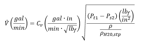
Since Flow Simulator’s valve element supports other loss coefficient types, use the above equation together with standard incompressible loss coefficient conversions to relate one form of loss coefficient to the others.
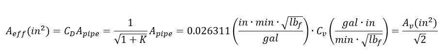
After conversion, the standard flow function is applied using effective area as the main driving loss parameter.
For compressible gas flows, choking must be considered. Because every valve has its own custom geometry, which even changes with the valve position, each valve has its own fluid Mach number profile. This means that every valve experiences choking at a different pressure ratio, and the critical pressure ratio depends on the valve position. In addition to loss coefficients (Cv, Av, Aeff, Cd, and K), another parameter needs to be introduced. This is the compressible gas choking correction factor. Three forms are supported (C1, XT, and CF). CF is equivalent to FL from the ISA nomenclature in reference 2.
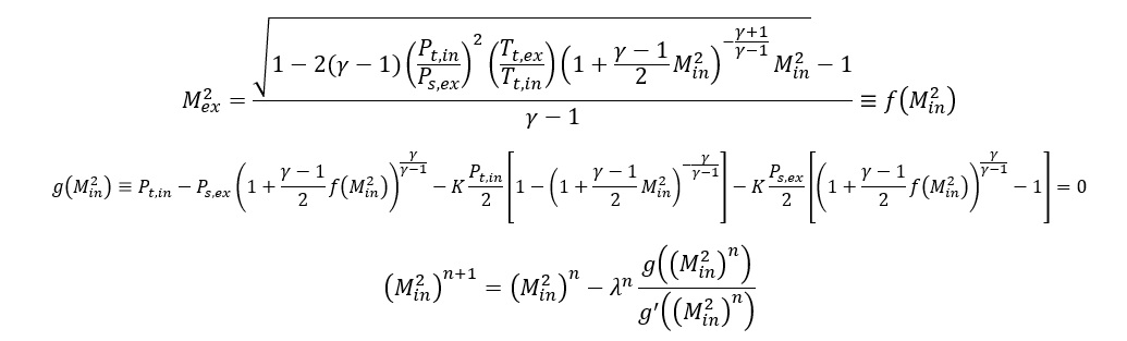
Before looking at the choking correction factor, focus on the subsonic flow equations. To solve for the valve element flow rate, you must solve the mass continuity equation and the momentum balance equation at the same time.
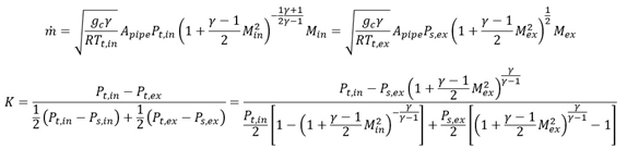
Rearranging the mass continuity equation yields the following function f, which
expresses exit Mach number in terms of inlet Mach number. Then f is inserted into
the momentum equation and the momentum equation is rearranged into a residual
function that must be driven to zero by changing inlet Mach number in order to reach
a converged solution. Finally, Newton’s method is applied to solve for inlet Mach
number. The method uses a relaxation parameter  that is generally equal to one (no relaxation) but drops
to 0.5 or lower if convergence is not reached with 20 iterations. Usually,
convergence is attained in 1 to 4 iterations.
that is generally equal to one (no relaxation) but drops
to 0.5 or lower if convergence is not reached with 20 iterations. Usually,
convergence is attained in 1 to 4 iterations.
Once the inlet Mach number is identified, the continuity equation is used to solve for mass flow rate, exit Mach number, and all other previously unresolved velocity, static temperature, and pressure quantities at inlet and exit stations.
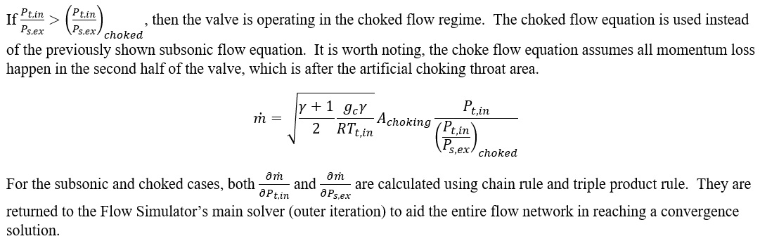
Before calculating subsonic flow rate however, you first need to determine if the flow is in the choked regime. For valves, choking happens more easily than ideal flow channels, and this is where the choking correction factor and the semi-empirical choking area formula come into use.
Incompressible liquid flows are also checked for choking. For a liquid, choking can occur when the static pressure in the valve is low enough for cavitation (vaporization) to occur. The incompressible flow for a valve is choked if:
Where FF is liquid critical pressure ratio factor. It is a ratio of vapor pressure of fluid at upstream flow conditions to thermodynamic critical pressure of the fluid, given by [2]:
If cavitation is detected, the valve element will use a downstream pressure equal to the vapor pressure, FF *PV, to calculate the flow rate.
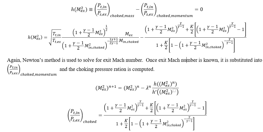
Next, the mass continuity equation and the momentum balance equation are reintroduced. However, this time you must rearrange and solve for the pressure ratio and substitute the inlet Mach number that corresponds to choked at the artificial choking throat area.
Additional Momentum Loss
For Additional Momentum loss, Reynolds Number correction, Portion of Upstream Dynamic Head loss, Exit K Loss refer Solver General theory section.
Valve Element Output Variables
Outputs in file with “res” extension. Output units controlled by user setting in “Output Control” panel.

| Name | Description | Units ENG, SI |
|---|---|---|
| FLOW: FLOW: %WREF & MASSFLOWRATE |
Flow rates in %WREF and [PPS]or [kg/s] | (None) & (PPS or kg/s) |
| VALVE_TYPE | Type of the valve information | - |
| VALVE_CHARACTERISTIC | Valve characteristics information
|
- |
| FLUID | Flow equation information
|
- |
| VALVEPOS | Valve position (% opening), copy of user input | % |
| PIPE_DIAM | Diameter of the pipe, copy of user input | inch, m |
| PIPE_AREA | Cross sectional Area of the pipe, copy of user input | Inch2, m2 |
| PIPE_PERIM | Pipe perimeter, copy of user input | inch, m |
| DQ_IN | Inlet dynamic head loss (copy of input) | inch, m |
| ELEMENT_THETA | Tangential Angle (Usually an echo of the user input but converted to radians.) |
radians |
| ELEMENT_PHI | Radial Angle (Usually an echo of the user input but converted to radians.) |
radians |
| REL_INLET_ANGLE | It is a relative inlet angle calculated based on upstream chamber velocity | Deg |
| INLET_MACH_NEEDED_FOR_CHOKING | Mach number at chocked flow.  Used to determining whether flow is subsonic or choked |
|
| CALCULATED_RESTRICTION_AREA_AT_THROAT | Calculated Area for Choked Conditions  |
inch, m |
|
Compressible Gas Correction Factors: C1= XT= CF= |
Compressible gas correction factors | (unitless) |
| Gas Factor Information | *Valve Compr. Gas Factor from … Information about gas factor calculations |
- |
| Loss Curve Information | *Valve Loss Curve taken from -1: User-Defined Loss Curve in Table #1 0: Auto-select best loss curve based on VALVE_TYPE 11: Angle Valve K Curve from D.S. Miller’s Internal Flow Systems 2nd Ed. Fig. 14.24 21: Ball Valve K Curve from D.S. Miller’s Internal Flow Systems 2nd Ed. Fig. 14.24 31: Butterfly Valve K Curve A from D.S. Miller’s Internal Flow Systems 2nd Ed. Fig. 14.19. 32: Butterfly Valve K Curve B from D.S. Miller’s Internal Flow Systems 2nd Ed. Fig. 14.19 33: Butterfly Valve K Curve C from D.S. Miller’s Internal Flow Systems 2nd Ed. Fig. 14.19 41: Gate Valve K Curve from D.S. Miller’s Internal Flow Systems 2nd Ed. Fig. 14.22 51: Globe Valve K Curve from D.S. Miller’s Internal Flow Systems 2nd Ed. Fig. 14.24 61: Sluice Valve K Curve from D.S. Miller’s Internal Flow Systems 2nd Ed. Fig. 14.22 71: Y-Valve K Curve from D.S. Miller’s Internal Flow Systems 2nd Ed. Fig. 14.24 |
- |
| KB_INPUT | (unitless) | |
| KC_INPUT |
|
(unitless) |
| CD_INPUT |
|
(unitless) |
| AEFF_INPUT | Pipe Area * CD_INPUT | Inch2, m2 |
| CV_INPUT | Valve Flow Coefficient | |
| AV_INPUT | Flow coefficient | Inch2, m2 |
| CG_INPUT |
|
|
| KB_RESULT | (PTIN - PTEX) / (0.5D0 * (PTIN - PSIN) + 0.5D0 * (PTEX - PSEX)) | (unitless) |
| KC_RESULT | (PTIN - PTEX) / (PTIN - PSVC) | (unitless) |
| CD_RESULT |
|
(unitless) |
| AEFF_RESULT | Pipe Area * CD_ RESULT | Inch2, m2 |
| FLOW REGIME |
Information about flow regime:
|
- |
| ELEMENT_RPM | Rotational speed of the restriction, RPM = 0 for Stationary | rev/min |
| RAD | Radius | in, m |
| ELEMENT_THETA_EXIT | Tangential Angle (Usually an echo of the user input but converted to radians.) |
radians |
| ELEMENT_PHI_EXIT | Radial Angle (Usually an echo of the user input but converted to radians.) |
radians |
| PTS | Driving pressure relative to the rotational reference frame (i.e. rotor) at the transition inlet. | psia, MPa |
| PSIN | Static pressure relative to the rotational reference frame (i.e.
rotor) at the transition inlet. Limited by critical pressure ratio for supersonic flows when inlet area is smaller than exit area. |
psia, MPa |
| PTEX | Total pressure relative to the rotational reference frame (i.e. rotor) at the transition exit including supersonic effects. | psia, MPa |
| PSEX | Static pressure relative to the rotational reference frame (i.e.
rotor) at the transition exit. Limited by critical pressure ratio for supersonic flows. |
psia, MPa |
| TTS | Total temperature of fluid relative to the rotational reference frame (i.e. rotor) at the transition inlet. | deg F, deg K |
| TSIN | Static temperature of fluid relative to the rotational reference frame (i.e. rotor) at the transition inlet. | deg F, deg K |
| TTEX | Total temperature of fluid relative to the rotational reference frame (i.e. rotor) at the transition exit. | deg F, deg K |
| TSEX | Static temperature of fluid relative to the rotational reference frame (i.e. rotor) at the transition exit. | deg F, deg K |
| QIN | Heat input. Positive values indicate heat added to the fluid; negative values indicate heat removed. |
BTU/s, W |
| INVEL | Velocity of fluid relative to the rotational reference frame (i.e. rotor) at the transition inlet. | ft/s, m/s |
| INMN | Mach number of fluid relative to the rotational reference frame (i.e. rotor) at the transition inlet. | (unitless) |
| INREYN | Reynolds number at the inlet. | (unitless) |
| EXVEL | Velocity of fluid relative to the rotational reference frame (i.e. rotor) at the transition exit. | ft/s, m/s |
| EXMN | Mach of fluid relative to the rotational reference frame (i.e. rotor) at the transition exit. | (unitless) |
| EXREYN | Reynolds number at the exit. | (unitless) |
| PTVC | Total Pressure at Vena Contracta | psia, MPa |
| PSVC | Static Pressure at Vena Contracta | psia, MPa |
| TTVC | Total Temperature at Vena Contracta | deg F, K |
| TSVC | Static Temperature at Vena Contracta | deg F, K |
| VCVEL | Vena Contracta Velocity | ft/s, m/s |
| VCMN | Vena Contracta Mach Number | - |
| VABS | Magnitude of the fluid total absolute velocity | ft/s, m/s |
| VTAN_ABS | Magnitude of the fluid absolute tangential velocity | ft/s, m/s |
| VAXIAL | Magnitude of the fluid axial velocity | ft/s, m/s |
| VRAD | Magnitude of the fluid radial velocity | ft/s, m/s |
| THTA_ABS | Fluid absolute tangential flow angle | rad |
| VREL | Magnitude of the fluid total velocity relative to the element | ft/s, m/s |
| VTAN_REF | Reference frame tangential velocity | ft/s, m/s |
| VTAN_REL | Magnitude of the fluid tangential velocity relative to the element | ft/s, m/s |
| VNORM | Magnitude of the fluid total velocity relative to the element | ft/s, m/s |
| THTA_REL | Fluid relative tangential flow angle | rad |
| TTABS | Absolute total temperature | deg F, K |
| TTREL | Relative total temperature | deg F, K |
References
- Miller, D, Internal Flow Systems, Miller Innovations, 1990
- ISA-75.01.01-2007, Flow Equations for Sizing Control Valves