Disk Pumping
Description
In a gas turbine, compressor and turbine blades are mounted on rotor disks. The flow over the disk gives rise to a boundary layer owing to the rotation of it, which pumps the fluid depending on the angular velocity of the flow with respect to the disk. The flow is pumped outward in case it rotates slower than the disk.
This section focuses on disk pumping beneath a forced vortex, where the flow rotates at a fraction of the angular velocity of the disk.
The disk pumping element models such situations and calculates the mass flow rate of this pumped flow over the disk.
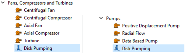
Disk Pump Creation in the Graphical User Interface
Disk Pumping Element Inputs
| Index | UI Name (*.flo Label) | Description |
|---|---|---|
| 1 | Number of Segments (NUMBER_SEGMENTS) | This option is displayed when you select Chamber
and Radii Tables from the Input Type. It signifies the number of segments the DP element is divided into; each segment being affected by a corresponding swirl chamber. |
| 2 | Rotor Index (RPMSEL) | Element rotational speed pointer. 1.0: Rotor 1, RPM = general data ELERPM(1). 2.0: Rotor 2, RPM = general data ELERPM(2). 3.0: Rotor 3, RPM = general data ELERPM(3). Default: Rotor 1 |
| 3-6 | (FUTURE) | |
| 7 | Mass Flux Equation (M_DOT_FLAG) | Select the equation used to calculate the mass flow rate for
each segment. Options include:
Default: Sultanian For more information, see Flow Rate Calculation. |
| 8 | Vortex ID (VORTEX_ELEM) | This option is displayed when you select Select
Vortex Element from the Input Type. You can either pick the vortex element or manually enter the vortex element ID that you want the disk pumping to be associated with. Using the user-selected vortex element, the solver automatically populates the Number of Segments, Swirl Chambers table, and Radii table. |
| 9 | Input Type: Select Vortex Element Or Chamber and Radii Tables (INP_METHOD) |
Default: Select Vortex Element |
| 10 | Mass Flow Multiplier (FLOW_MULT) | Factor to be multiplied to the mass flow rate calculated from
the equation. This helps adjust mass flow rate if you want to
have some variation factor to it. Default: 1.0 |
| 11 | Swirl Chambers (Table: CHAMBER) | This option is displayed when you select Chamber
and Radii Tables from the Input Type. This is a table with the number of rows equal to the Number of Segments. In this table, you can enter the swirl chambers for each segment or pick the chambers. Note: The chambers must be entered or
selected from the entry chamber to the exit chamber in
the order of flow.
|
| 12 | Radii (Table: RADII) | This option is displayed when you select Chamber
and Radii Tables from the Input Type. This is a table with the number of rows equal to the Number of Segments + 1. In this table, you can enter the swirl chamber radii for each segment or pick the radii. Note: The radii must be entered or
selected from the entry chamber to the exit chamber
radii in the order of flow.
|
Disk Pumping Element Theory: Overview
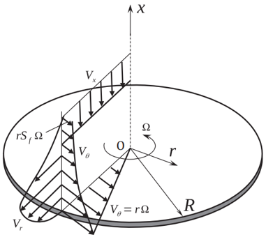
Figure 1 illustrates the boundary layers forming on a rotating disk when the fluid outside the boundary layer itself rotates as a forced vortex at a fraction of the disk angular velocity. The swirl factor Sf lies between 0 and 1. The maximum pumped flow rate occurs when Sf = 0. When Sf = 1, the fluid gets into solid-body rotation with the disk with no pumping flow. The boundary layers in this case become turbulent for Re = , the local rotational Reynolds number.
The disk pumping element is divided into multiple segments; each segment has a vortex or inertial chamber associated to it. The beginning and end of each segment is represented as a “station” with one more station than the number of segments. Each station has a radius which is determined by the chamber associated to the segment. The swirl factor for each segment is calculated. The angular velocity for each segment is retrieved from the reference rotor the disk is connected to. The swirl factor must be relative to the surface RPM of the disk. Using the fluid properties and inner and outer radii, the local Reynolds number is calculated.
Once the local Reynolds number is calculated, calculate the mass flow rate of the disk pumping element.
Disk Pumping Element Theory: Flow Rate Calculation
There are two methods to calculate mass flow rate:
SULTANIAN APPROACH
OWEN ROGERS APPROACH
- ζ = Mass flow rate factor
- Ω = Disk angular velocity
- ρ = Density
- µ = dynamic viscosity
- r = radius of the station
- Sf = Swirl Factor of the segment
The calculation of the total mass flow rate of the disk pumping:
Disk Pumping Element Outputs
| Name | Description | Units |
|---|---|---|
| SEG | The segment number | (number) |
| XK | Swirl Factor for the vortex/inertial chamber associated with the segment. | (number) |
| RE | Reynolds number for the segment. This is an average of the local Reynolds numbers at stations of the segment. |
(unitless) |
| REF_RPM | RPM of the reference rotor associated to the Disk pumping element. | Revolutions/minute |
| XK_CHMBR | The vortex/inertial chamber associated with the segment. | (number) |
| INNER_R | Inner radius of the segment. Usually, an echo of the input unless modified inside Flow Simulator. |
Inch, m |
| OUTER_R | Outer radius of the segment. Usually, an echo of the input unless modified inside Flow Simulator. |
Inch, m |
| MDOT | Mass flow rate of each segment. | lbm/s, kg/s |
References
- Sultanian, Bijay K, Gas turbines: internal flow systems modeling, Cambridge University Press, 2018.
- Benra, F.-K., Dohmen, H. J., & Schneider, O. (2008). Application of an Enhanced 1D network model to calculate the flow properties of a Pre-Swirl Secondary Air System. Volume 4: Heat Transfer, Parts A and B. https://doi.org/10.1115/gt2008-50442.