The friction in the Flow Simulator element can be calculated
by the given equation, where:
stands for the calculated friction based on the user-selected friction mode (Abauf,
Swamee), friction type (Fanning or Darcy), and Re (to determine whether it is in a
turbulent region, or in a laminar region).
If ReDh < ReTurb, laminar friction calculations take place,
otherwise, the turbulent friction calculation routine is used.
Nomenclature
Subscripts
f: friction
F: fanning
Re: Reynolds number
D: darcy
FMULT: friction multiplier
turb: turbulent flow
ε: sand grain roughness
lam: laminar flow
A: Cross sectional area
Abuaf: Abuaf friction relation
L+: Inlet station + 1/9 of 2nd station
Smooth: smooth surface
XMU: dynamic viscosity
Rough: rough surface
W: mass flow rate
SJ: Swamee-Jain approximation
X: station length
Dh: hydraulic diameter
L: equivalent diameter
Laminar Friction
Calculates the friction coefficient for laminar flow in shaped ducts based on the
references Yunus A. Cengel, 2006 and Bruce Munson, 2005.
Friction coefficient for hydrodynamically fully developed flow can be calculated
as:
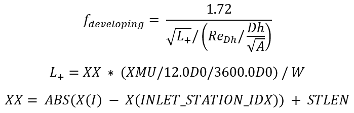
For a Tube Element, Laminar Friction Inlets effects can be accounted. Friction
coefficient for hydrodynamically developing flow with “Muzychka Yovanovich Laminar
Inlet Effects” can be calculated as:
The friction coefficient for combining developing flow and fully developed flow can
be calculated as:
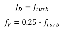
Darcy type friction is calculated as
Fanning type friction is calculated as:
Turbulent Friction
Calculates the turbulent friction for smooth or rough walls.
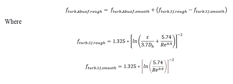
Abuaf Friction Relation
The Abuaf friction relation should generally be used for smooth walled tubes.
In Flow Simulator, you have the option
to use the Abuaf friction relation together with wall roughness. The
following adjustment equation is used:
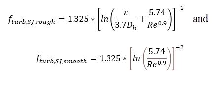
Swamee-Jain Approximation of the Colebrook-White Equation (Moody
Diagram)
The Darcy and Fanning type frictions are calculated
as:
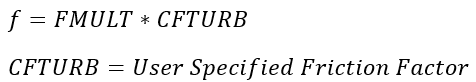
User-specified Friction Factor
Roughness
Surface roughness values can be entered in four different measurement types. The
roughness values are converted to sand grain roughness equivalents using the
following equations from table 1 of reference 63.
ε=5.863∗Ra,
Ra=Average Absolute Roughness
ε=3.100∗Rrms,
Rrms=Root Mean Square Roughness
ε=0.978∗Rzd,
Rzd=Peak to Valley Roughness
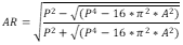
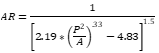
Non-Circular Shapes in Flow Simulator Tubes
The friction factor and heat transfer coefficient (HTC) correlations were developed
for circular pipes. The traditional method to use these correlations on non-circular
shapes is to calculate a hydraulic diameter based on the shape area and
perimeter.
The errors associated with this method can be +/-40% for laminar flow but less for
turbulent flow, +/-15% (see White, ref 3).
A more accurate option is to adjust the hydraulic diameter with a friction factor
ratio (see White, ref 3). The effective hydraulic diameter can then be
used in the friction factor and HTC correlations.
The following table summarizes the relationship between the Dh based on 4*A/P and the
effective hydraulic diameter.
Shape
Effective Dh Equation
Aspect Ratio (AR)
Circle
AR=1
Rectangle
AR=b/a
Ellipse
AR based on area and perimeter of the ellipse.
Isosceles Triangle
AR based on area and perimeter of the triangle.
Annulus
AR=b/a
Freeform
(Arbitrary- Shape)
AR based on area and perimeter of freeform shape using a
rectangle equation.
See Blevins (ref 15) and Muzychka et al. (ref 50) for
additional information.
If the compressible tube, advanced orifice, and incompressible tube have a cross
sectional shape that is not circular, the equations in this table are used for the
effective hydraulic diameter equation.
Two-phase Flow Friction
The friction factor for two-phase flow (liquid and gas) in an incompressible tube can
be calculated using two options. The homogenous approach uses the laminar and
turbulent equations shown above with fluid properties based on the liquid/gas
mixture. The second approach uses friction equations developed by Friedel (ref
64).
(quality)
Recommended to use if
Turbulator Friction
The friction factor for a turbulated surface can be calculated for the advanced or
incompressible tube element. These friction factors are available when the tube's
wall surface finish input is set to “Turbulated Surface”. The turbulated friction
correlations are used for the tube wall sides that have turbulators. The walls
without turbulators will use the smooth wall correlations from above.
The friction factor can come from four different references based on tube and
turbulator geometry. The correlations and suggested use cases are described
below.
Webb Circular Tube (ref. 1)
Use this correlation for circular tubes with
square shaped ribs. This correlation and the Han correlations use the
law-of-the-wall similarity for flow over rough surfaces. See the
reference for more explanation.
TS Ravi Circular Tube (eq 11.2 in ref 2.)
Use this correlation for
circular tubes and all rib profiles. This correlation uses a statistical
approach to correlate many experimental results. It is good for a wide
range of geometries but may not be as accurate as the other correlations
for geometries specific to them. This correlation calculates a
multiplier to a smooth tube friction. The smooth friction correlation
also comes from reference 2.
Limits:
Han 90 deg, 2-sided rectangular tube (ref 3.)
Use this correlation for a
rectangular shaped passage with ribs on two sides. This is for ribs that
are perpendicular to the flow only.
Limits:
Han Angled, 2-sided rectangular tube (ref 4 and 5)
Use this correlation
for a rectangular shaped passage with ribs on two sides. This is for
ribs that are 30 to 90 degrees (perpendicular) to the
flow.
Exponent, m, depends on the
rectangle aspect ratio.
For 0.25<w/h<1 (ref
4):
For 1<w/h<4 (ref
5):
Limits:
Where:
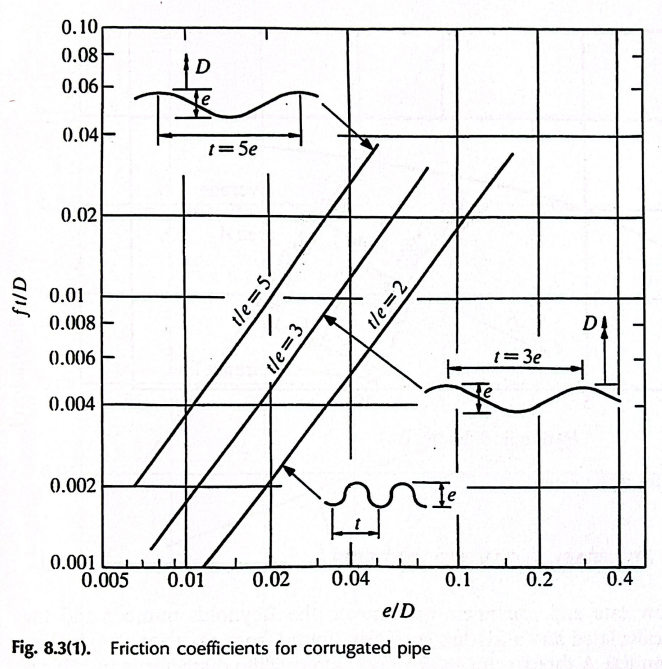
Miller Corrugated Tube (ref 7)
Use for a corrugated circular pipe. The
ribs have a semi-circular shape and extend around the entire
pipe.
Friction is based on fig 8.3 of reference 7:Figure 1.
Limits:
Pin Fin Friction
The friction factor for a surface with Pin-Fins can be calculated for the advanced or
incompressible tube element. These friction factors are available when the tubes
wall surface finish input is set to “Pin-Fins”. The Pin-Fin friction correlations
are used for all of the tube wall sides, including the sides defined as smooth.
The friction factor is calculated using a single correlation so far. More may be
added in future releases.
Metzger Pin-Fin Friction (ref 8.)
This friction is for a pin fin array
that is staggered. Typically used for narrow passages with pin height
close to the passage width (like found on cooled turbine blade trailing
edge passages).
If
If
This is the friction for one row of
pins. The friction must be multiplied by the number of pins in the flow
direction.
Limits:
1000 < < 100,000
Pin Height ~ Pin Diameter
(Pin crossflow spacing)/(Pin Diameter) ~2.5
1.5 ≤ (Pin flow direction spacing)/(Pin Diameter) ≤ 5
Parallel Rotating Tube Friction
The friction factor in a tube that is parallel to the rotation center line is
described in this section. The advanced tube is the only tube element that can use
this friction equation. The equations come from reference 6.Figure 2.
Where
Axial Reynolds number:
Rotational Reynolds number, J:
The values for a, b, and c come from Table 1 in reference 6.
L/D
Flow Type
a
b
c
Validity Range
10.6
Laminar-like
3.98
0.16
-0.63
4.57x10⁻⁴ < J0.25/Reax
< 6.00x10⁻³
10.6
Turbulent-like
0.064
0.023
-0.093
7.50x10⁻⁵ < J0.25/Reax
< 4.57x10⁻⁴
31.8
Laminar-like
2.30
0.21
-0.62
1.12x10⁻³ < J0.34/Reax
< 1.20x10⁻²
31.8
Turbulent-like
0.108
0.058
-0.17
1.20x10⁻⁴ < J0.34/Reax
< 1.12x10⁻³
For completeness, the correlation includes an equation for no rotation,
The values for x and y come from Table 2 in reference 6.
L/D
Flow Type
x
y
Validity Range
10.6
Laminar-like
7.91
-0.60
900 < Reax < 9880
10.6
Turbulent-like
0.076
-0.095
9880 < Reax < 51,000
31.8
Laminar-like
7.37
-0.63
900 < Reax < 7000
31.8
Turbulent-like
0.138
-0.16
8000 < Reax < 51,000
Linear interpolation is used to blend the different equations for laminar to
turbulent transitions and for Tube Length/Diameter effects.
Friction Correlation References
Webb, R. L., Eckert, E. R. G., and Goldstein, R. J. "Heat Transfer and
Friction in Tubes with Repeated-Rib Roughness", Int. Journal of Heat and
Mass Transfer, 14 (1971).
Ravigururajan, T.S., "General correlations for pressure drop and heat
transfer for single-phase turbulent flows in ribbed tubes", Iowa State Univ,
Thesis, 1986.
Han J.C., "Heat Transfer and Friction Characteristics in Rectangular
Channels with Rib Turbulators", Journal of Heat Transfer, ASME (1988).
Han, J. C., Ou, S., Park, J. S. and Lei, C. K. " Augmented Heat Transfer in
Rectangular Channels of Narrow Aspect Ratios with Rib Turbulators" ,
International Journal of Heat Mass Transfer, 32, (1989).
Han, J. C. and Park, J. S. "Developing Heat Transfer in Rectangular Channels
with Rib Turbulators", International Journal of Heat Mass Transfer, 31,
(1988).
Johnson, A.R., & Morris, W.D., 1992. “An experimental investigation into
the effects of rotation on the isothermal flow resistance in circular tubes
rotating about a parallel axis”, International journal of heat and fluid
flow, 13(2), pp. 132-140.
Miller, D. (1990). Internal Flow Systems - Miller Innovations.
Metzger, D. E., Fan, Z. X., and Shepard, W. B., 1982b, "Pressure Loss and
Heat Transfer Through Multiple Rows of Short Pin Fins," Heat Transfer 1982,
Vol. 3, U. Grigull et al., eds., Hemisphere, Washington, pp. 137-142.