View Seam Weld Reactions
Display a table of seam weld resultant forces and stresses.
Total contact forces and average stresses are displayed for each weld but seam weld resultant forces and stresses at the throat can also be evaluated per unit length. The number of data points for this evaluation is determined automatically by the length of the weld. Resultant forces and stresses per unit length can be used with seam weld design standards, specifically Eurocode 3 (EN 1993-1-8: Eurocode 3: Design of Steel Structures, Section 4.5.3).
Force/Moment
- In the Project Tree, open the Analysis workbench.
-
In the Analysis Workbench, select
 Weld
forces > Seam weld reactions.
Weld
forces > Seam weld reactions.
- In the Seam weld reaction dialog, select the Force/Moment tab.
- Click Evaluate to calculate Force/Moment components along the weld length for all welds. This estimates the peaks (maximum and minimum) among all the welds in the model.
- Set the desired threshold value as a failure criterion for Force per unit length.
- Click Validate to see the status of each weld after evaluation.
- Select any column header to sort the table.
- Select any row to display a Force and Moment summary along with their vectors in graphics.
- Optional:
Use
 (Zoom) to
focus the modeling window on the chosen weld.
(Zoom) to
focus the modeling window on the chosen weld.
-
View a plot of a seam weld's reaction per unit length over the length of the
weld.
- In the plot window, select Save as to save results as an image or text file.
Stresses
- In the Project Tree, open the Analysis workbench.
-
In the Analysis Workbench, select Weld
forces > Seam weld reactions.
- In the Seam weld reaction dialog, go to the Stresses tab.
- Optional:
By activating the option Include bending moments in stress
evaluation, bending moments due to loading can be included while
calculating for stresses.
Tip: It is recommended to activate the Include bending moments in stress evaluation option when the seam weld loading is influenced by bending moment or torsion with respect to the perpendicular axis of the weld.
- Optional: Enable Use absolute values for maximum stress evaluation to ensure that stress calculations consider the maximum absolute values regardless of sign.
-
Click Evaluate to calculate various stress components
along the weld length for all welds.
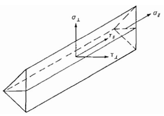
Figure 1. 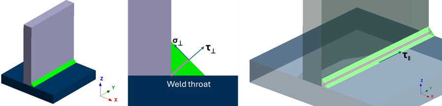
The below equations are as per the bending theory:
Normal stress due to normal force ( ) along the vertical direction of the weld:
Normal stress due to bending moment ( ) along the vertical direction of the weld:
Shear stress due to shear force ( ) along the vertical direction of the weld:
Shear stress due to shear force ( ) along the parallel direction of the weld:
Shear stress due to moment ( ) along the vertical direction of the weld:
Shear stress due to moment ( ) along the parallel direction of the weld:
Equations used to calculate the maximum stress for each component:
Maximum normal stress along the vertical direction of the weld,
Maximum shear stress along the vertical direction of the weld,
Maximum shear stress along the parallel direction of the weld,
Where,- Normal stress vertical to the weld direction
- Shear stress vertical to the weld direction
- Shear stress parallel to the weld direction
- AT
- Weld throat area
- Fx, Fy, Fz
- Force components solved using the reaction forces from the contact between seam weld and the part
- Mx, My, Mz
- Moment components solved using the reaction moments from the contact between seam weld and the part
- ry
- Distance from the centre of weld to the location where the stress is calculated along the weld length
- rx
- Width of the weld throat
- Iw
- Moment of inertia of the welds
- Jw
- Polar moment of inertia of the weld
Equivalent stress is calculated based on the following equation:
Equivalent stress should be lesser than the standard values calculated. An example based on EN 1993-1-8 Eurocode 3 gives the following equation:
For the standard values calculated based on the Eurocode example, the terminologies are mentioned below where,
- fu
- Nominal ultimate tensile strength of the weaker part joined
- Appropriate correlation factor
- Set the desired threshold value as a failure criterion for the stresses (normal stress, shear stress, and equivalent stress).
- Click Validate to see the status of each weld after evaluation.
-
For average stress calculations, the ability to divide each weld into further
sections can be activated by checking Include weld section
stresses. Then you can enter a value for Section
length to throat thickness ratio.
This value ensures a weld is not constrained to a particular welding standard.
- Select any column header to sort the table.
- Optional:
Use (Zoom) to
focus the modeling window on the chosen weld.
-
View a plot of a seam weld's stresses per unit length over the length of the
weld.
- In the plot window, select Save as to save results as an image or text file.
- Case study 1
- To calculate the stress components for a weld along its throat which
connects a beam using double-sided fillet weld. Vertical force of 30 KN
is applied along +Z-axis and constrained at the base plate.
Figure 2. 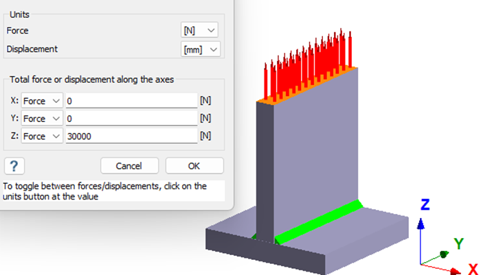
Force and moment components for one of the welds is taken from the Reaction/contact force dialogue as shown below.
Figure 3. 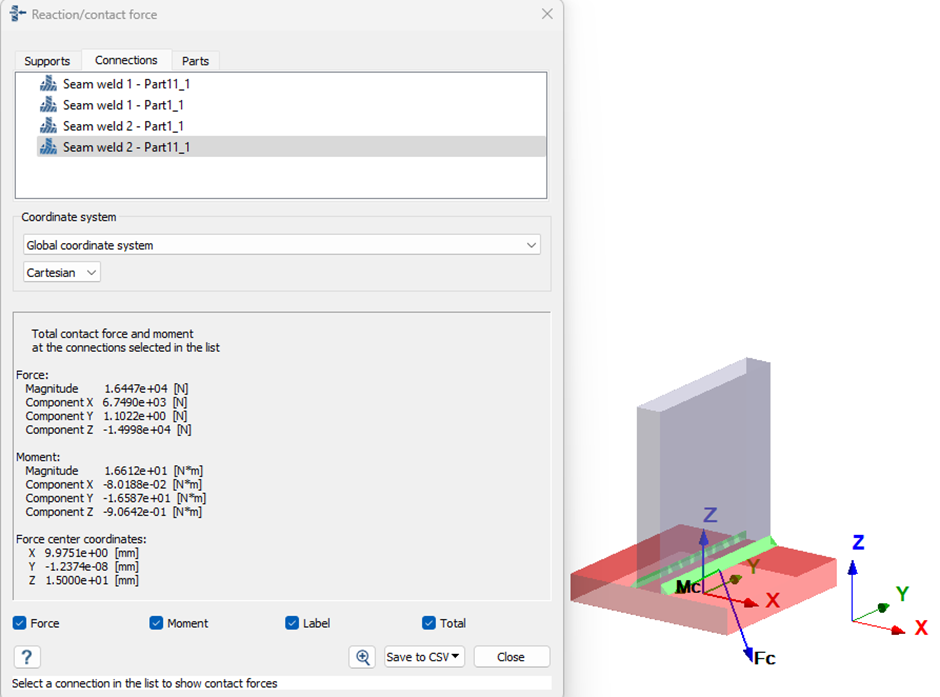
Table 1. FX = 6.75E+03 N FY = 1.10E+00 N FZ = -1.50E+04 N MX = -80.1880 Nmm MY = -16587.0000 Nmm MZ = -906.4200 Nmm Resolving the forces and moments for the throat of the weld with respect to global coordinated system as shown in the below table.
Table 2. -5832.0430 N 1.1022 N -1.54E+04 N -697.5319 Nmm -16587.0000 Nmm Mz' = -MX*0.707+MZ*0.707 -584.146024 Nmm Now, calculating the normal stresses and shear stresses for the weld throat.Note: Stresses due to moment are ignored as they are negligible.Normal stress perpendicular from axial:
Where,
Shear stress perpendicular from axial:
Shear stress parallel from shear:
Equivalent stress:
Table 3. Comparison between SimSolid and hand-calculated values Stress components SimSolid (MPa) Analytical (MPa) Delta (%) σ⊥ 44.03 43.50 1 τ⊥ 16.70 16.50 1 σequivalent 52.90 52.03 <2 Note: Bending stresses were ignored as they are negligible, hence the comparison was made with an average stress value. - Case study 2
-
To calculate the stress components for a weld along its throat which connects a beam using double-sided fillet weld. Moment of 1e7 N-mm is applied along z-axis on the base surface of the vertical plate as shown below and constrained at the base plate.
Figure 4. 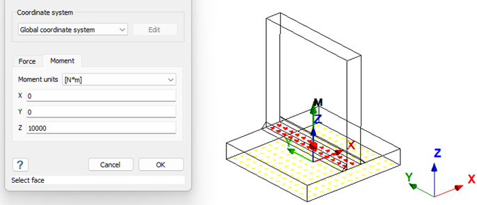 Force and moment components for one of the welds is taken from the Reaction/contact force dialogue as shown below.
Figure 5. 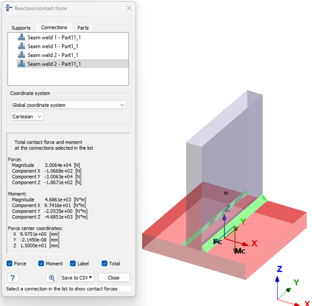
Table 4. FX = -106.6800 N FY = -30063.0000 N FZ = -186.7100 N MX = 97416.0000 Nmm MY = -2053.5000 Nmm MZ = -4685100.0000 Nmm Resolving the forces and moments for the throat of the weld with respect to global coordinated system as shown in the below table,
Table 5. -207.4267 N -30063.0000 N -56.6 N -3243492.5880 Nmm -2053.5000 Nmm Mz' = -MX*0.707+MZ*0.707 3381238.812 Nmm Now, calculating the normal stresses and shear stresses for the weld throat.Note: Both stresses due to forces and moments are considered as the seam weld is exposed to torsion.Normal stress perpendicular from axial:
Where,
Normal stress perpendicular from bending:
Maximum normal stress perpendicular:
Shear stress perpendicular from shear:
Shear stress perpendicular from torsion:
Maximum shear stress perpendicular:
Shear stress parallel from shear:
Shear stress parallel from torsion:
Maximum shear stress parallel:
Equivalent stress:
Table 6. Comparison between SimSolid and hand-calculated values Stress components SimSolid (MPa) Analytical (MPa) Delta (%) σ⊥max 556.79 550.60 1 τ⊥max 560.80 572.5 2 σequivalent 1129.37 1139.76 <1 Note: Bending stresses were considered for stress calculation, hence we are considering the corner location (ry) due to maximum stress at that location. Compared with maximum values from SimSolid seam weld reaction table.