Wind Load
Wind load is the force exerted by wind on a structure.
It's a type of pressure that varies with wind speed, height, and the shape of the object. SimSolid can apply wind loads based on user-defined parameters, such as wind speed and direction, to simulate the effects of wind on buildings, signs, or other structures.
Theory of Wind Loads
In structural analysis, wind load denotes the force imposed by wind on a structure.
Wind load is influenced by factors like height above the ground and velocity. These forces can profoundly impact the stability and structural integrity of structures and buildings. SimSolid plays a crucial role in modeling wind loads on structures by considering key factors such as wind speed, air density, directionality, frictional drag, and shape factor. By incorporating these parameters, SimSolid facilitates the evaluation of pressure exerted on surfaces exposed to the wind, contributing to accurate calculations of structural deflection.
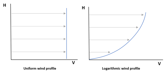
A pivotal influence on wind load considerations is the wind profile. SimSolid supports two distinct profiles: Uniform and Logarithmic. These profiles serve as mathematical models, elucidating the uniform distribution or logarithmic progression of wind speed concerning the height above the ground (H) within the atmospheric boundary layer.
- u
- Shear velocity (Default = ~0.5)
- Von Karman constant (Default = ~0.41)
- H
- Height above ground where velocity was measured
- Wind pressure
- Air density
- V
- Speed of the wind
- C
- Shape factor
For the surfaces which are parallel to the wind direction includes frictional drag ( ) is calculated by, the following equation.
Create Wind Profile
Define the wind profile using one of the following methods
- In the Project Tree, click the structural analysis in which the wind load BC will be applied.
-
On the Analysis Workbench, click
 (Wind load).
-
Click Create profile and create a wind profile in one of
the following ways.
To Do this Import from external CSV - In the dialog, click Import CSV.
- Browse to the desired file and click Open.
Note: The file contents must have a header row followed by two or more rows of data. Each row has two to three values. Values must be separated with commas. The first is speed and the second is height above ground.- Speed
- Height above ground
- 0
- 0
- 10
- 4
- 38
- 9
- 47
- 13
- 61
- 18
Create from standard template function - In the dialog, click Standard.
- In the Function type drop-down, select the desired template.
- For Uniform, specify Speed (V) and Height above ground (H).
- For Logarithmic, define Shear velocity (u), von-Karman constant (k) and Height above ground (H).
- Click OK.
Create manually - In the dialog, click Add row. A new row will appear in the dialog's table.
- Click in the row under Point #, Speed, or Height above ground to activate a text box.
- Enter desired values.
- Click OK.
Create Wind Load
Apply wind load based on wind profile for structural analysis
- In the Project Tree, click on a structural analysis to open the Analysis Workbench, then select Structural linear or Structural non-linear.
-
On the Analysis Workbench, click
 Pressure > Wind load.
The Wind Load dialog opens.
Pressure > Wind load.
The Wind Load dialog opens. -
Click Create profile and create a wind profile in one of
the following ways.
To Do this Import from external CSV - In the dialog, click Import CSV.
- Browse to the desired file and click Open.
Note: The file contents must have a header row followed by two or more rows of data. Each row has two to three values. Values must be separated with commas. The first is speed and the second is height above ground.- Speed
- Height above ground
- 0
- 0
- 10
- 4
- 38
- 9
- 47
- 13
- 61
- 18
Create from standard template function - In the dialog, click Standard.
- In the Function type drop-down, select the desired template.
- For Uniform, specify Speed (V) and Height above ground (H).
- For Logarithmic, define Shear velocity (u), von-Karman constant (k) and Height above ground (H).
- Click OK.
Create manually - In the dialog, click Add row. A new row will appear in the dialog's table.
- Click in the row under Point #, Speed, or Height above ground to activate a text box.
- Enter desired values.
- Click OK.
- Click the Ground tab to place the origin of the wind load. Coordinates can be either manually entered or it can be placed by dragging the origin point from the modeling window.
- Optional: Define Wind direction and Height axis in their respective tabs.
- Optional:
Enter values for Air density, Friction
coefficient, and Shape factor.
By default, they are set to 1.2 kg/m3, 0.01, and 1 respectively.
- Optional:
To protect parts from the wind load that are obstructed by other parts, select
the Enable shielding checkbox.
Note: Without Enable Shielding, wind load is exerted on all components, regardless of whether their surfaces facing the wind source are obstructed by other parts within the assembly.
- Click OK.