Geometry Import/Representation
Learn geometry import settings best practices.
SimSolid does not directly import CAD surface or solid geometry. Instead, it uses a more efficient method involving faceted geometry. The geometry is converted into faceted volumes, and analysis is conducted based on the boundaries defined by these volumes. The precision of the faceted geometry—and thus the accuracy of the analysis—is influenced by the resolution settings selected during the import process.
SimSolid provides several preset resolution options—Standard, Enhanced, and Fine—along with a Custom setting that allows for adjustments in angular and chordal deviations. Opting for higher resolution settings, such as Fine or Custom, increases the number of facets used to represent the geometry, which can lead to longer solution times. While these higher resolutions can enhance accuracy, they may not always be necessary or optimal for every analysis. It is crucial to choose the import settings that best match the complexity of your geometry and the goals of your analysis to ensure an effective balance between detail and computational efficiency.

- Best Practice
- For stress analysis, it’s crucial to avoid rough facets that can lead to inaccurate stress concentrations. In these cases, opting for Enhanced or Fine resolution settings is recommended to ensure greater detail and accuracy. However, if the primary goal is to evaluate stiffness, the Standard import setting is typically sufficient and more efficient for most scenarios.
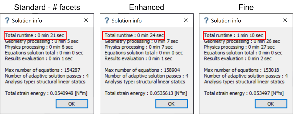
Increased import resolution leads to longer run time, especially when using Fine setting.
Recommended Cases for Increasing Resolution
- Parts with Curvatures: Higher resolution is
particularly important when working with parts that curvatures or complex
geometries.
The left side of the figure below shows a model with rough facets. This low-resolution representation can miss critical details of the curvature and often results in unrealistic stress concentrations or singularities. The geometry is not well-represented, and significant features may be overlooked.
The right side of the figure shows the same model with increased resolution. This higher level of detail provides a smoother, more accurate depiction of the curvature, capturing the true shape of the geometry. It reduces the risk of unrealistic stress concentrations and ensures a more precise analysis of the overall volume.
Figure 3. 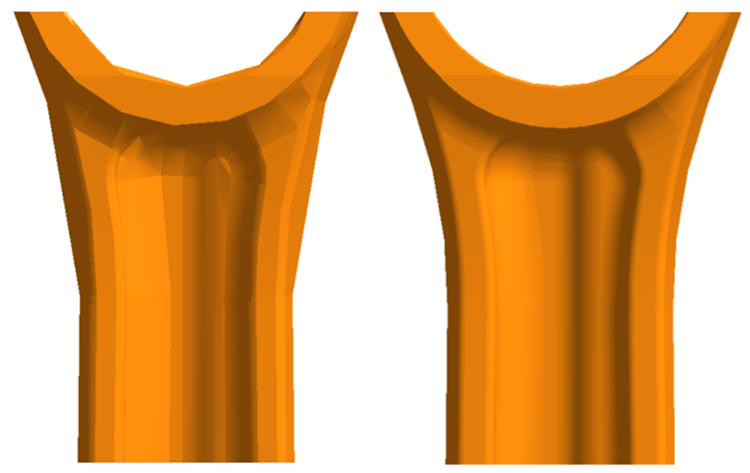
- Best Practice
- When dealing with parts with curvatures or complex features, using Enhanced or Fine resolution settings is crucial. This approach not only improves the accuracy of stress predictions but also ensures that the geometric details are faithfully represented, avoiding issues with missing or distorted features.
- Holes: Holes are common regions where stress
concentrations occur and are often the focus of analysis. To avoid issues
associated with rough facets, which can introduce singularities and
unrealistic stress concentrations, it’s important to ensure proper
resolution.
The figure below shows an extreme case where a hole is inadequately represented due to insufficient facets, resulting in the hole appearing as a polygon (pentagon or hexagon) instead of a smooth circle. This rough representation leads to stress singularities at the sharp corners of the polygon.
Figure 4. 
- Best Practice
- For parts with holes or cylindrical features, inspect the geometry visually. If the geometry is not adequately represented, opt for Enhanced or Fine resolution settings during import. This ensures that the hole is accurately depicted and helps prevent singularities caused by rough facets, leading to more realistic and reliable stress analysis results.
- Thin-Walled Structures: For thin-walled components
such as sheet metals or plastics, it’s crucial to use higher resolution
settings to accurately capture their geometry, especially for structures
with wall thicknesses less than one millimeter. Thin-walled structures are
prone to self-intersections, where the bottom face of a thin wall penetrates
the top face or vice versa. Self-intersections are problematic because they
result in non-physical scenarios that can cause numerical instabilities in
SimSolid. To avoid self- intersections,
import models with Enhanced or Fine resolution whenever possible. If it is a
geometry issue, address these problems by repairing the geometry before
importing it into SimSolid. Self-intersections
can be detected early by running a geometry error check in SimSolid.
In addition to identifying issues, SimSolid also provides tools for repairing sheets directly within the software. Sheets can be fixed for problems such as self-intersections and inconsistencies in thickness. The repair process is iterative, as changes made to one region may impact the thickness in other areas. Therefore, repair process may need to be executed several times to resolve all issues effectively.
The figure above shows regions with variation in thickness—some areas being thinner or thicker than nominal—and instances of self-intersections. All these issues can be addressed within SimSolid.
Figure 5. 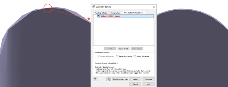
- Best Practice
- To properly import thin-walled structures, use enhanced or fine import settings. After importing, run the geometry error check to identify any self-intersections. If any issues are found, utilize the repair tools within SimSolid to correct self-intersections and address inconsistencies in thickness. Additionally, ensure that any CAD issues are resolved before importing the model into SimSolid. This ensures that the thin walls are represented accurately and helps to avoid inaccuracies in stress analysis.
Overall Guidelines
- Import Settings:
- Thin-Walled Structures, Curvatures, and Holes: Always import these models with Enhanced or, if necessary, Fine resolution to ensure accurate representation and stress analysis.
- Stress Analysis: Use Enhanced or Fine settings for models where stress details are crucial to obtain precise results.
- Geometry Check:
- Defects: Before proceeding to analysis, verify that there are no geometry defects such as unwanted voids, self-intersections, or sharp and rough facets.
- Repair: Utilize SimSolid repair tools to address any identified issues for sheets to ensure a clean and accurate model.
- Assembly Considerations:
- Merged Parts: Avoid merging parts in the assembly as this can lead to complications and inaccuracies in the analysis.
- Defeatured Parts: It’s advisable not to defeature parts before importing them into SimSolid, as this can result in unnecessary singularities at sharp regions created by the defeaturing process. Instead, import the original CAD model as is, which ensures a more accurate and effective analysis.