Connection Fidelity
Connection tools in SimSolid and connection best practices.
SimSolid supports a variety of connection types including:
- Regular Contact-Based Connections: Standard contact interactions between surfaces.
- Seam Welds: Connections representing welded seams.
- Spot Welds: Area-based weld connections typically used in sheet metal assemblies.
- Laser Welds: Connections that simulate the effects of laser welding.
- Virtual Connectors: A growing range of virtual connectors such as joints, bushings, superelements and remote mass, which help in modeling complex interactions and constraints.
Regular Connections
- Regular connections are represented as point clouds at the interface between interacting parts. These point clouds indicate where contact interactions occur.
- Connections can be created automatically or manually. In either case, SimSolid automatically determines the gap and penetration tolerance. Resolution is based on default settings.
- Properly tuning the proximity tolerance and resolution is crucial for creating realistic connections, leading to more accurate load paths and better overall simulation results.
- Tolerances
-
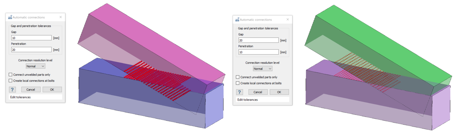
- Connections are established based on proximity criteria. If two parts have faces within the defined gap/penetration tolerance window, a connection can be established between them.
- Gap tolerance:
- Too Large: A large gap tolerance can result in connections being made in undesired areas, potentially leading to an over-stiff model and unrealistic simulation results.
- Too Small: A very small gap or penetration tolerance can result in parts remaining disconnected or unstable, affecting the accuracy and reliability of the analysis.
- Resolution
- The density of the point cloud at the connection interface indicates the
strength and quality of the connection. A higher number of points
ensures a well-defined connection between parts, which is crucial for
predicting accurate load paths, avoiding stress concentrations, and
resolving convergence issues in non-linear contact analysis.
- Selective Use: Only use Increased, High,
or Extreme resolution in areas where detailed connection
definition is necessary. This prevents unnecessary computational
overhead.
Figure 2. 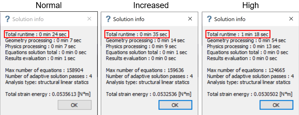
- Aspect Ratio Check: Use the Aspect Ratio option in the review connections window to assess connection quality. A connection with an aspect ratio less than 0.001 is considered well-defined.
- Connection Layers: Ensure there are at least two layers (lines) of connection points between the parts to provide a robust connection.
- Avoid Discrete Points: Ensure that
connections do not contain discrete points, as these can lead to
stress concentrations and inaccuracies in the analysis.
Figure 3. 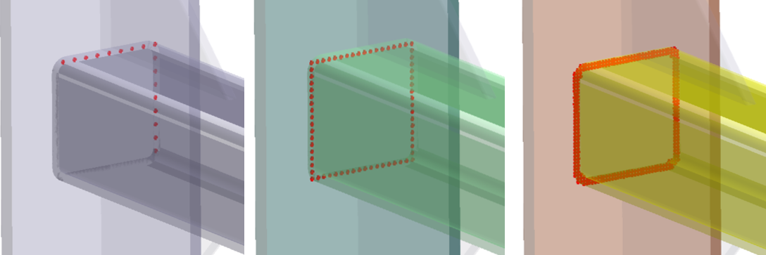
- Selective Use: Only use Increased, High,
or Extreme resolution in areas where detailed connection
definition is necessary. This prevents unnecessary computational
overhead.
Improper Connection Examples
- Incorrect Load Paths: A connection with insufficient
resolution or improperly set tolerances can cause incorrect load paths. This
may result in an inaccurate distribution of forces and moments throughout
the assembly, affecting its overall performance.The below figures is a model with two plates connected by a single layer of connection points. When analyzing this setup, it can be observed from the image that the vertical plate behaves as if it is hinging around the connection line.
Figure 4. 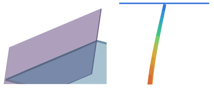
In such cases, it is advisable to increase the connection resolution. As shown in the image, increasing the resolution adds multiple lines of connection points, which results in a more robust bonded contact along these points during the analysis.Figure 5. 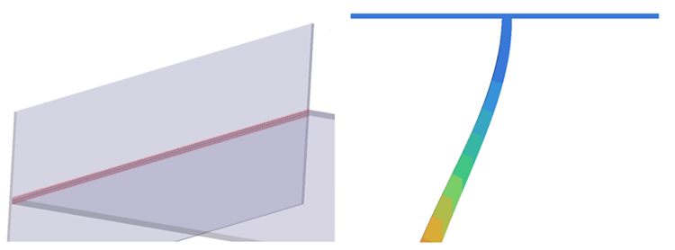
- Unwanted Stress Concentrations: Inadequate point
cloud density or poorly defined connections can lead to localized stress
concentrations, which are unrealistic and may not reflect the actual
behavior of the assembly.In the example below, the first figure illustrates localized stress concentrations due to inadequate connection points. However, the second figure features a higher density of connection points which displays a more even distribution of stress.
Figure 6. Inadequate connection point cloud 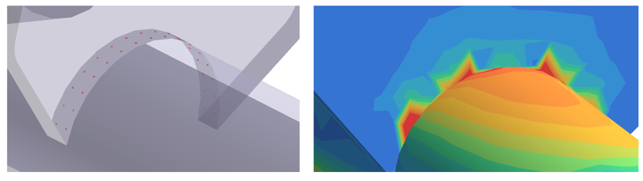
Figure 7. Adequate connection point cloud 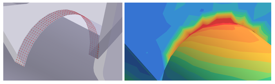
- Convergence Issues in Non-Linear Analysis: In non-linear contact analysis, poorly defined connections or discrete points can lead to convergence problems. The solver might struggle to find a solution due to inconsistencies in the connection definition, causing the analysis to fail or produce unreliable results.
Connection Tools in SimSolid
SimSolid provides several tools to simplify the creation
and management of proper connections:
- Show Disconnected Groups:
- Lists all disconnected groups of parts, allowing you to either delete, suppress, or connect them.
- Select the disconnected groups you want to address and use the
Connect option to establish connections without
having to recreate other connections.
Figure 8. 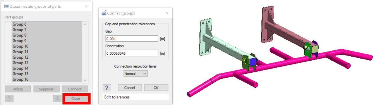
- Review Regular Connections:
- Provides a comprehensive list of all regular connections within the design study, including detailed information on each connection.
- Use this tool to sort connections by gap/penetration, number of points or aspect ratio to identify and address problematic connections.
- The aspect ratio option in the review connections window helps
evaluate the quality of connections. Connections with an aspect
ratio less than 0.001 are considered well-defined and ensure good
connectivity between parts.
Figure 9. 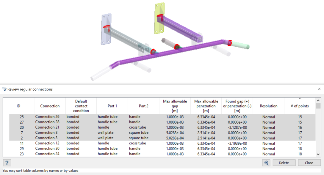
Seam Welds
Seam welds are represented as prismatic or trapezoidal solids at the overlapping feature lines between parts. They can be created either manually between parts or by importing CAD welds or lines via an .xml file.
Use of SimSolid seam welds provides superior adaptation methods compared to simply using a solid body with bonded contact. It is highly recommended to use SimSolid welds wherever possible.
However, there are two scenarios where seam welds cannot be created in SimSolid:
- Imported solids where the centerline is significantly displaced from the feature line
- Convex edges
Overall Guidelines
- Regular connections
-
- Use Automatic Connections Wisely: Keep tolerances low to ensure accurate connections.
- Apply Increased Resolution Connections Judiciously: Use higher resolution connections only when necessary to avoid unnecessary computation.
- Utilize Connection Check Tools: Use these tools to quickly connect groups and identify problematic connections.
- Bolt Shank Connections: Always use sliding connections at the bolt shank to accurately simulate interactions.
- Seam welds
-
- Prefer SimSolid Welds: Use SimSolid seam welds whenever possible for the best results.
- Virtual connections
-
- Avoid Large Faces: Refrain from applying virtual connections to large faces to ensure accurate simulation and avoid potential issues.