Explores best practices to ensure high-fidelity results in SimSolid.
SimSolid operates as a multi-pass adaptive solver that
effectively works with unsimplified CAD geometries. Its workflow is similar to that
of traditional finite element analysis tools, comprising pre-processing, the
solution (or solver) phase, and post-processing. The following guidelines can
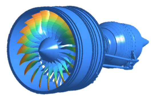
improve accuracy and enhance the reliability of simulations.Figure 1.