Format and Execute Options

Analysis > Options > Solution Settings > Format and Execute Options

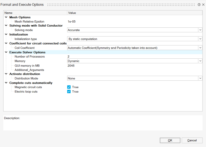
The Format and Execute Options allow the user to set the options which will be taken by Flux solver (in batch) to solve the current solution.

Mesh options

Mesh Relative Epsilon allows to define the limit to consider two nodes as superimposed or not.

The Mesh absolute Epsilon is computed by multiplying the Mesh Relative Epsilon (1e-5 by default) by the diagonal of the bounding box of the solution bodies.

The distance between two nodes is compared to the Mesh absolute Epsilon value: if it is lower then the nodes are considered as superimposed.

Initialization

The transient solution can be initialized either with zero or with static computation.

The initialization with zero can lead to a numeric transient which distorts the solving process:
  • Increase of calculation time
  • False results over the first time steps
  • Convergence issues, especially in 3D
That happens especially in the following situations:
  • There are magnets or non-null sources of current at the initial time step t=0s
  • There are solid conductors and/or coil conductors coupled with electric circuit

The sources quantities gap at t=0s leads to very high derivative values at this time step which generates the numeric transient.

The initialization by static calculation is characterized by particular calculation conditions for the first time step: conditions, which permit to annul all the terms in d/dt at the step t = 0s.

These conditions are summed up in the table below.

Element of the device Hypotheses / conditions of calculation at t = 0 s
in the finite elements domain in the electric circuit
Solid conductor Active (circuit coupling) Skin effects, proximity effects are not taken into consideration (= non magnetic conducting regions) DC resistance (electric conduction resistance)
Passive (no circuit coupling) Induced currents are not taken into consideration (= non conducting magnetic region) -
Coil conductor Current in coil (=circuit current) Resistance (of coil conductor)
Element of the device in the electric circuit
Resistor Resistance (values of the Resistor component)
Inductor Inductance replaced by a resistor with small resistance
Capacitor with initial voltage Uc Capacitor replaced by a voltage source * (U = Uc)
without initial voltage Capacitor replaced by an open circuit

Solving mode with Solid Conductor

In a MAC3D or MT3D solution with solid conductor (either passive or active), it is possible to select either Accurate solving mode (default choice) or Fast solving mode.

The nodal variables are set to the first order for the Fast solving mode and to the second order for the Accurate solving mode.

If the Accurate solving mode is selected and if the SimLab mesh is in first order, then a message will be posted to confirm the mesh order increase to second order.

Coefficient for circuit connected coils

A coil is defined by two objects:
  • an electrical component of stranded coil conductor type defined in the circuit
  • a coil geometrically defined entity to define the shape of coils
A coil is described in a finite element domain that can be bounded by symmetries and/or periodicities.
  • from an electric point of view, there is only one electrical component
  • from a geometric point of view, there is an "original" coil (the one described in the FE domain) and its "duplicates" by symmetry and/or periodicity

In this situation, the electrical component is a component that comprises several geometric coils.

To compute the magnetic flux through this component (i.e. through the "original" coil and its "duplicates"), Flux evaluates:
  • the coefficient CM, which takes into account the number and types of symmetries and/or periodicities
  • the field Conductors in series or in parallel, which takes into account the configuration type of associated conductors (all in series, all in parallel).

In the Automatic mode which is suitable for most cases, the coefficient CM takes into account the number and types of symmetries and/or periodicities.

But it is possible to define manually the coefficient CM defined either as an integer or a fraction.

An example which needs a manual CM definition is a speed sensor defined with symmetry/periodicity, but the coils must not be duplicated. Then CM is defined by the value 1.

The 3 possible choices are explained in the table below:

Option Description
Automatic coefficient (symmetry and periodicity taken into account) CM is automatically computed with taking active symmetries and active rotation periodicities of the problem into account.
Imposed coefficient (integer)

CM is an integer:

CM = N

N is the number of repetitive patterns described in the finite elements domain

(The finite elements domain corresponds to 1/N fraction of the real device)

Imposed coefficient (fraction)

CM is a quotient of 2 integers:

CM = N1/N2

The finite elements domain corresponds to 1/N1 fraction of the real device.

N1 is the number of repetitive patterns described in the finite elements domain

N2 is the number of repetitive patterns supplied by the electric circuit

Execute Solver Options

The Execute Solver Options define the options used at Flux solver execution:
  • Number of Processors used to parallelize the solving process
  • Memory used by Flux solver. By default, the memory is set to Dynamic memory allocation. It is possible to switch to a user defined memory (static memory) and specify the amount of memory to allocate
  • GUI memory defined statically by a given memory amount
  • Additional_Arguments is an advanced option to add additional arguments information like system memory, PEEC memory and so on. Input should be space separator. Example: -fluxncores 4 -memsizn3_mb 6000 -memsizc3_mb 200

Complete cuts automatically

When magnetic or conducting bodies have hole(s), magnetic cuts or electric cuts may be required to have good results.

When this option is enabled (default choice), at solve, Flux executes the automatic cuts creation algorithm before running the Flux solving.

For more information, please check Automatic Cuts creation for 3D Transient Magnetic and 3D Magnetic AC solutions