Cell Naming Order
![]()
Description
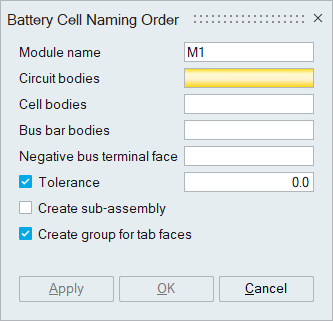
This tool is used to name the cells in the module based on the circuit configuration.
Module name
Users need to specify the module name that will prefix the series and parallel numbers.
Circuit bodies
All the bodies that are part of the electrical circuit needs to be selected. Cooling channels and other components that are not part of the circuit should be excluded from the selection.
Cell bodies
Cell or core bodies that are to be renamed should be selected.
Bus bar bodies
Bus bars connecting the cells in series and parallel are to be selected.
Negative bus terminal face
Reference terminal face should be selected from the negative bus bar of the module to specify the circuit direction.
Tolerance
Tolerance needs to be specified for module without node connectivity i.e., shared entities.
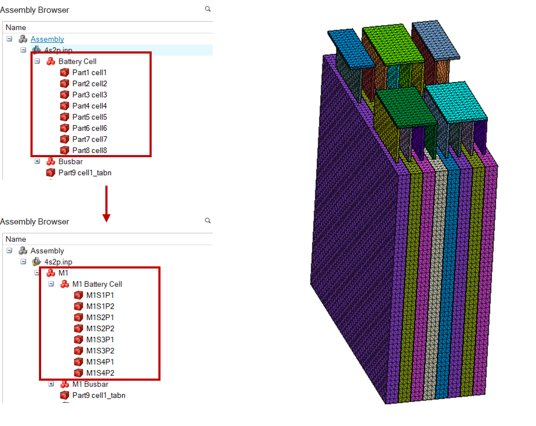
Create sub-assembly
This option is used to create sub-assembly structure using the input module name and group the cells and bus bars under the module.
Create group for tab faces
This option is used to create face groups for the positive and negative tabs automatically. Users can optionally input the tab bodies or faces for group creation.
- If the components are partially connected or some of the bodies are disconnected, user still need to input the gap tolerance for cell naming.
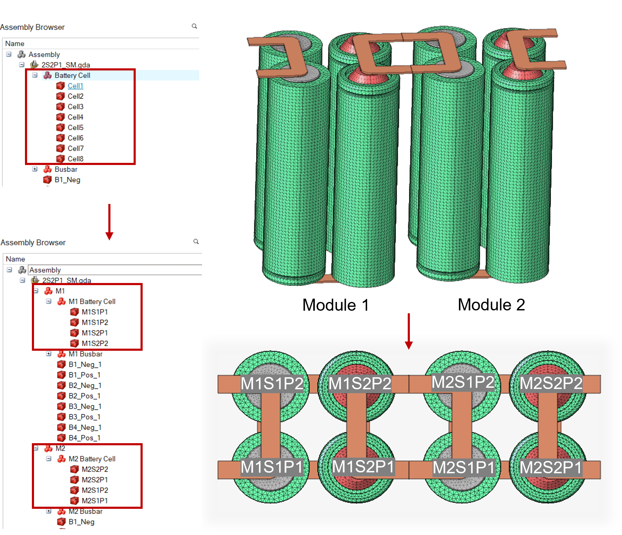
Example 1: Cylindrical Cells
Example 2: Pouch Cells